UCM buildingSMART International Logo
  • No results found
  • Use cases
  • Co-Creation Space
  • Community
    • buildingSMART
      • buildingSMART International
      • buildingSMART Austria
      • buildingSMART Benelux
      • buildingSMART Germany
      • buildingSMART Switzerland
    • Organizations
      • HSLU
    • Collaboration Partners
      • Companies
      • Associations & Institutions
      • Experts
  • en
    • en
    • de
    • fr
  • Login
Location
buildingSMART Switzerland Andreasstrasse 5 8050 Zurich (Switzerland)ucm@buildingsmart.ch
Company
HomeAbout usCommunityTraining
Resources
Use casesCo-creation spaceRelease notesFAQ
buildingSMART Logo
Copyright © 2025 buildingSMART. All rights reserved.
ContactPrivacy and Cookie StatementTerms and Conditions
Small IconAI Chat

    3D Modeling of Existing Asset Based on Point Clouds (Scan2BIM)

    Comments

    Loading comments...

    NOT REGISTERED YET?


    Register for the Use Case Management Service for free to start creating your first use case.


    Registered users can use the download area and the comment functions.

    3D Modeling of Existing Asset Based on Point Clouds (Scan2BIM)
    Document Type
    Use Case
    GUID
    E4541133-68BC-40B2-B634-B5B5E0A049FE
    Identifier
    BIMSpeed_UC3_CARTIF
    Life Cycle Stage
    ISO 22263
    Revision
    1.1.0
    Project Status
    Approved
    Maturity Level
    Example
    Published on
    Mar 4, 2022
    Last Change
    May 10, 2022
    Publisher
    BIM Speed
    Authors
    • Sonia Álvarez-Díaz
    Home
    Use cases
    3D Modeling of Existing Asset Based on Point Clouds (Scan2BIM)

    Use Case Document Definition

    Exchange Requirements

    Imprint

    Project Group

    • Sonia Álvarez-Díaz (CARTIF Technology Centre)
    • Román-Cembranos, Javier (CARTIF Technology Centre)

    Copyright

    All documents are licensed as "Creative Commons Attribution-NonCommercial-ShareAlike 4.0 International License" as Attribution - non-commercial distribution - under the same conditions
    For further information see: creativecommons

    Handling

    These documents do not claim to be complete. Nor are they to be understood in the sense of a recommendation or guideline that is generally valid from a legal point of view, but are intended to support the client and contractor in applying the BIM method. The use cases must be adapted to the specific project requirements. The examples given here do not claim to be complete. Information is based on practical experience and should therefore be regarded as best practice and not generally applicable. As we are in a phase in which definitions are only just emerging, the publisher cannot guarantee the accuracy of individual contents.

    Management Summary

    This document aims at describing '3D Modeling of Existing Asset Based on Point Clouds' use case which is implemented as part of BIM-SPEED EU Horizon2020 project, under grant agreement No. 820553, https://www.bim-speed.eu/en using the 3DASH Tool developed by https://www.cartif.es/en/. This use case allows to obtain the As-Built BIM model of the building based on the 3D point cloud obtained on site in the first phase of the renovation process.

    Purpose and Scope

    The ‘3DASH Tool’ implemented as part of BIM-SPEED project is developed with the need for the objectives set by the BIM-SPEED Project. It helps in:

      • Time reduction in the generation of walls in BIM from point clouds.
      • Accuracy in the generation of walls from point clouds due to the fact it is a mathematical process based on algorithms.

    Description

    Life Cycle Stages

    ISO 22263

    BIM Objectives & Benefits

    A tool that supports the creation of As-Built models using point clouds as data for the generation of BIM models using REVIT software with these users benefits:

    • Time reduction: both to generate As-Built models and to compare with previous existing models, or to generate these models if you do not have previous documentation.
    • Accuracy: the tool gives a high accuracy since it is a mathematical process based on algorithms for the detection and generation of walls using point clouds, compared to the manual process that would be for the user to generate the walls using as a template the point clouds, as it would never have the same accuracy in the selection of the points.

    Delimitation

    The tool needs a manual process by the user to check and edit the types of walls generated in case there is any overlap between them, but even so, this time would be less than the time it would take to manually do the whole process.

    Prerequisite / Framework Conditions

    • Autodesk Revit Website. Available online: https://www.autodesk.es/products/revit/overview.
    • BIM-SPEED (2021) 1: Methods for architectural, structural, thermal 3D data acquisition of existing buildings. BIM-SPEED Consortium, Berlin, Germany. See https://www.bim-speed.eu/en/results (accesed 08/07/2021).
    • BIM-SPEED (2021) 2: BIM Connectors for interoperability between different BIM tools and with the BIM-SPEED Platform. BIM-SPEED Consortium, Berlin, Germany. See https://www.bim-speed.eu/en/results (accesed 08/07/2021).
    • BIM-SPEED training materials area. Available online: https://www.bim-speed.eu/en/training-materials 

    Abbreviations

    • 3DASH: 3D Modeling Based of Existing Asset based on Point Clouds
    • BIM: Building Information Modeling
    • GUI: Graphical User Interface
    • IFC: Industry Foundation Classes

    Images

    Description

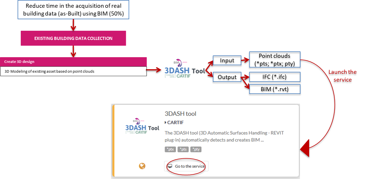
    The exchange requirements of the 3DASH are explained and shown in the image below:

    INPUTS:

    1. To launch the tool you need to download the 3DASH add-in file, and to install it in REVIT following the instruction of the Readme.txt file included.
    2. Obtain point clouds: The extension of the point clouds must to be .ply/.pts/.ptx.


    OUTPUTS:

    1. REVIT file: the walls created in a .rvt file.
    2. IFC file: The IFC can be created with the REVIT IFC exporter.

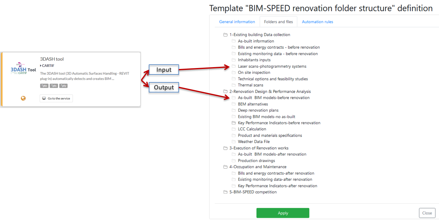
    These exchange requirements will be included in the folder structure defined in the BIM-SPEED platform, as shown in the image below:


    Images

    • image (1).png (png | 141.04 KB)
    • 3DASH_ExchangeRequirements.png (png | 163.62 KB)
    • 3DASH_ExchangeRequirementsFolders.png (png | 241.78 KB)

    Process

    Process diagram

    Overall process

    Description

    The overall process for 3DASH Tool is presented in the figure below. The procedure starts with collecting the 3D point clouds by the user acquired by laser scanning or photogrammetry systems. The overall process is further explained through its implementation on two demonstration sites.


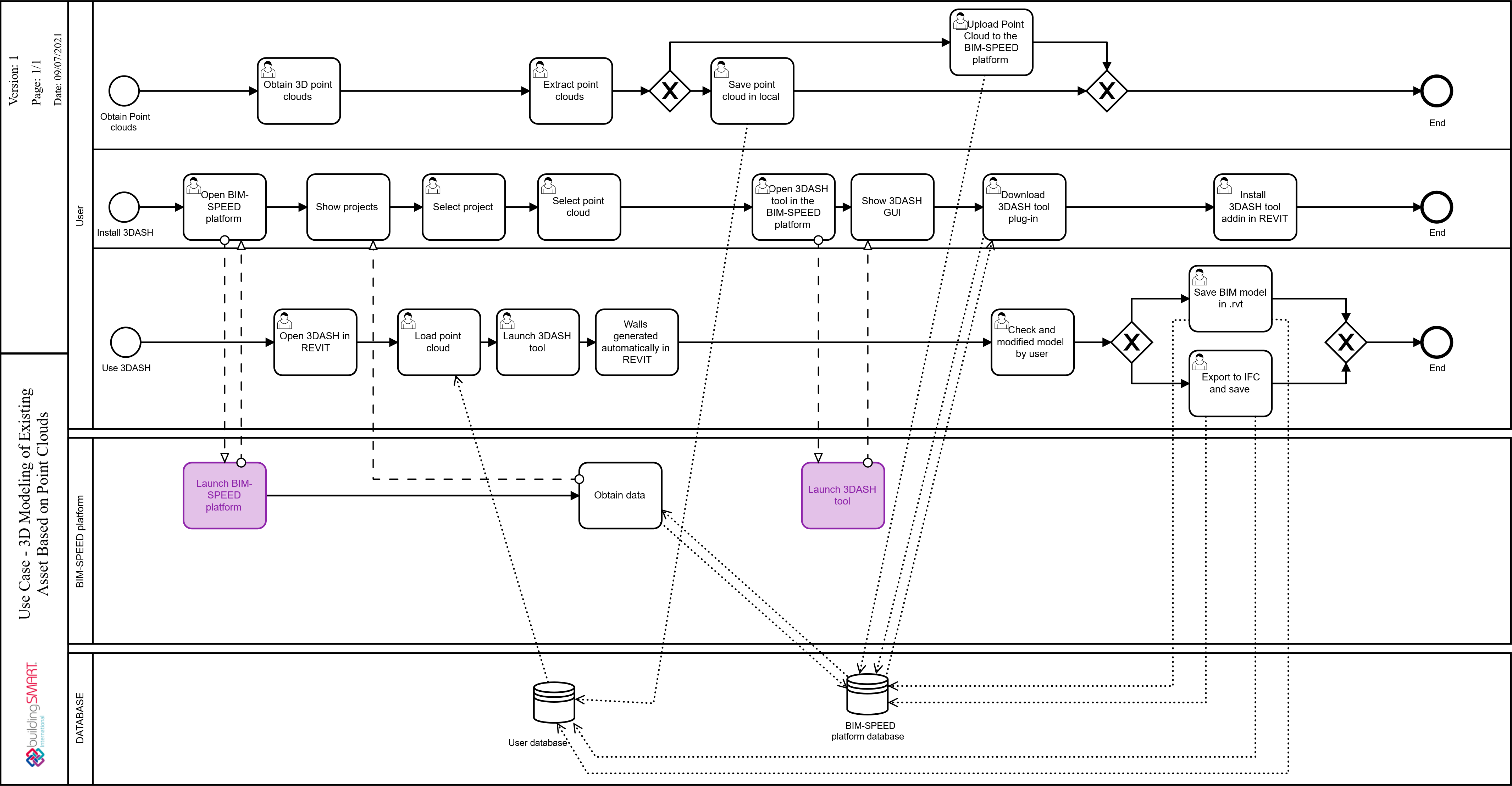
    As shown in the image above, there are three different parts involved in the process: the user, the BIM‑SPEED platform and the databases:

    • The user has to start three different process if it is the user’s first time using the tool:
      1. Obtain Point Clouds: First, the user has to obtain the 3D point clouds and transform them to PLY, PTS or PTX format.
      2. Install 3DASH plug‑in: The user has to launch the 3DASH Tool in the BIM‑SPEED platform to download the 3DASH add in and install the add in in REVIT.
      3. Launch the 3DASH Tool in REVIT.
    • BIM-SPEED platform: The BIM-SPEED platform allows to launch different services hosted on it, being able to launch the 3DASH GUI (Graphical User Interface) from the platform following the user’s commands.
    • Databases: There are two different databases in the process:
      1. User database: The user can save the data in its local database.
      2. BIM‑SPEED platform database: The user can upload and download data from BIM-SPEED platform.

    The details of the implementation of this tool in two demonstration cases are covered in the next section.

    DEMONSTRATION SITE – Jazdy Konnej, WARSAW, POLAND

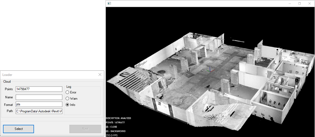
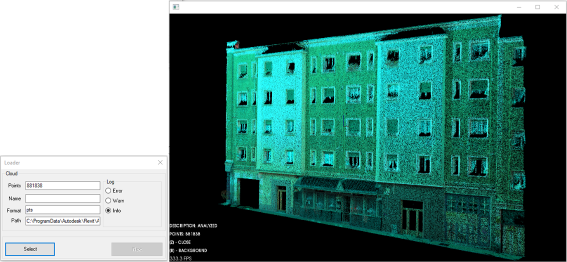
    The demonstration site is located in Warsaw, Poland. The building is an underpass. The point clouds upload to the tool in the first step ‘Analyzed’ is shown in the image below:


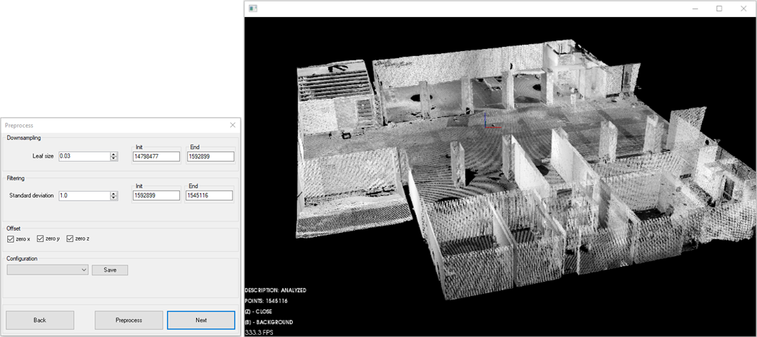
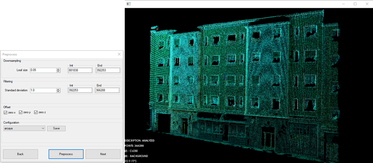
    The second step is the pre-processing process where several parameters are selected, the results of which is shown in the following image:

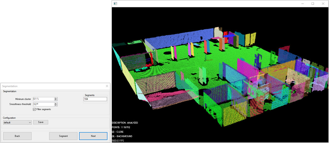
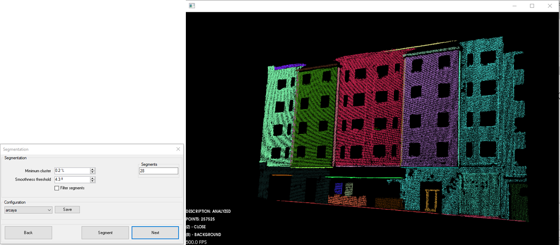
    In the segmentation step, the user can modify different parameters such as the smoothness threshold which indicates the maximum deviation between the normals of the neighboring points. The results for the Warsaw demo is shown below:


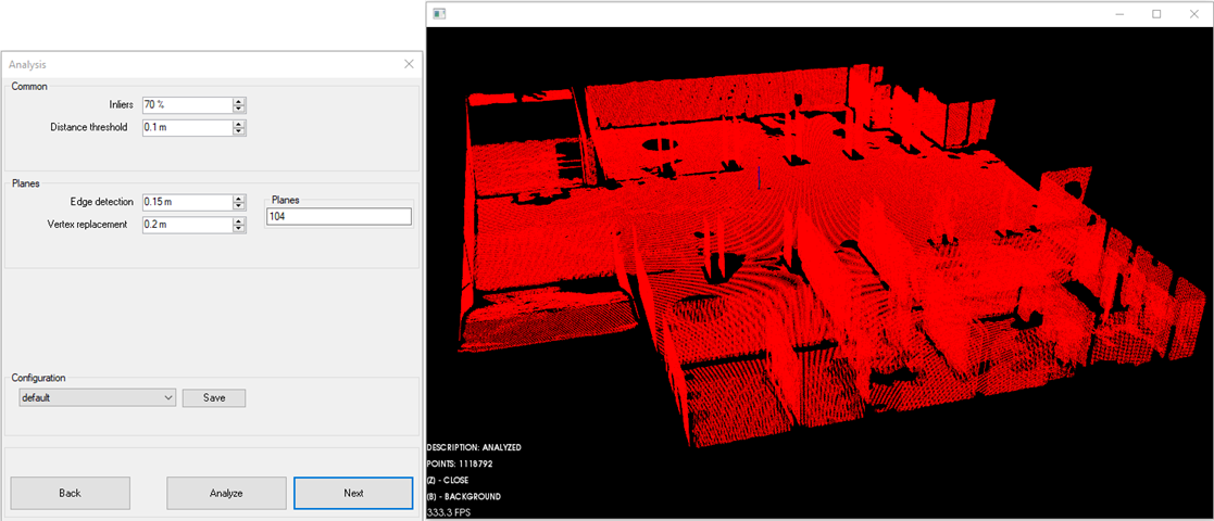
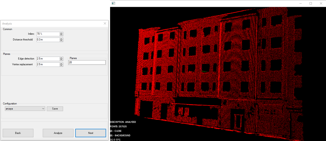
    The analysis step makes it possible to determine, among other parameters, the maximum distance between a point and the virtual plane to which it belongs. The results for the parameters selected in the Warsaw demo are shown below:

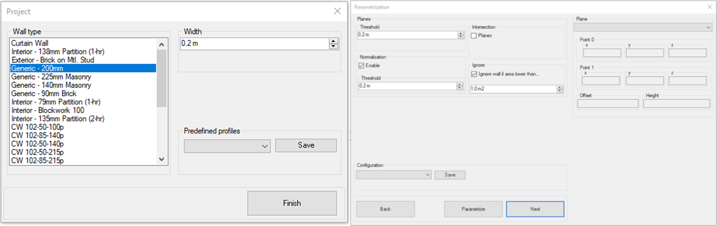
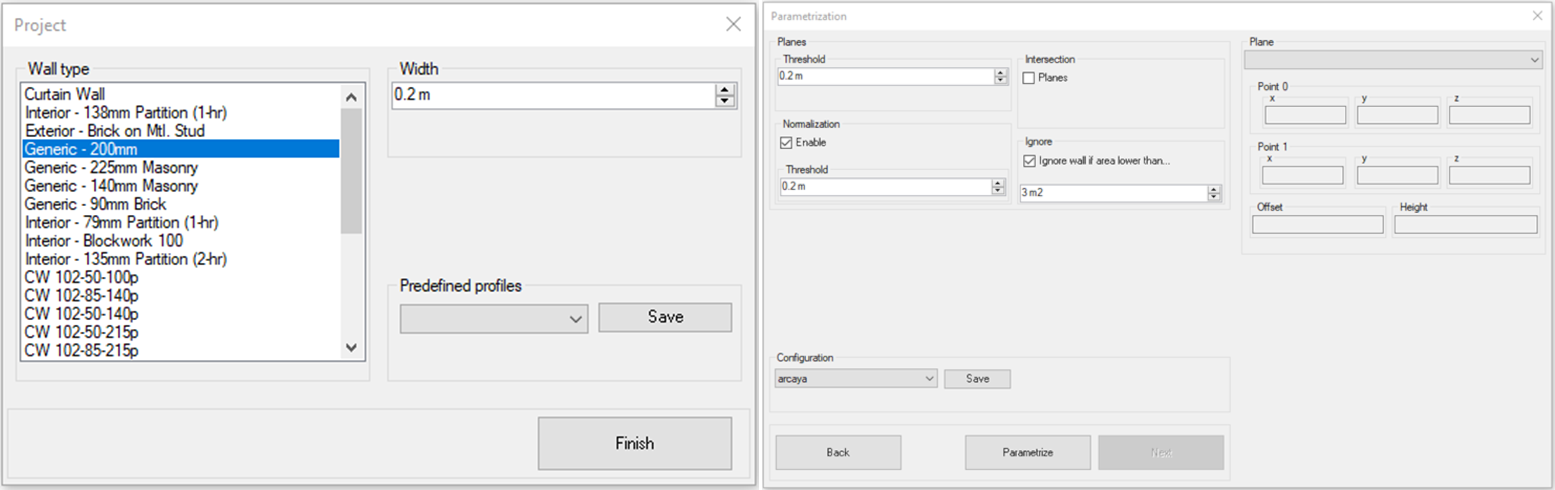
    Finally, the user can select the wall type to be applied in all the walls generated by the tool, as shown in the following images:

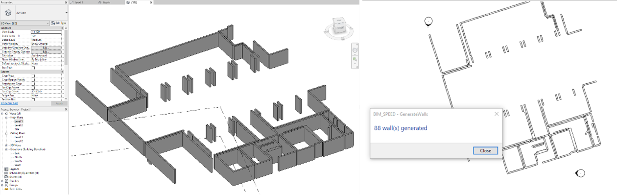
    With the options selected by the user in all the process, 88 walls have been generated and the time spent for the automatic generation was 77 seconds (excluding the time spent by the user in selecting parameters). The final result obtained for the Warsaw demo is show below:

    More information about this demonstration can be found in the training area of the BIM-SPEED website https://www.bim-speed.eu/en/training-materials and in the YouTube channel https://youtu.be/pJB1pGj1I34.

    DEMONSTRATION SITE – ARCAYA 5, VITORIA, SPAIN

    The second demonstration site of the use case 3DASH4Scan2BIM process has been carried out with the Vitoria demo, the building ARCAYA5. This demo is a residential building located in the city of Vitoria-Gasteiz, Spain. The steps are the same as those identified in the previous demonstration, so only the results are shown below:


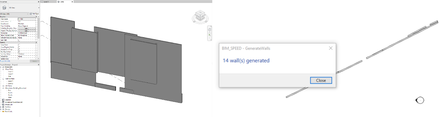
    In this case, the point cloud of the building was only of the main façade, obtaining 14 walls with the 3DASH tool. The time spent for the automatic generation was 18 seconds (excluding the time spent by the user in selecting parameters).

    Images
    • 3DASH_Arcaya5_Analysis.png (png | 315.25 KB)
    • 3DASH_Arcaya5_Analyzed.png (png | 641.20 KB)
    • 3DASH_Arcaya5_Parameterization.png (png | 148.03 KB)
    • 3DASH_Arcaya5_Pre-pro.png (png | 672.72 KB)
    • 3DASH_Arcaya5_results.png (png | 84.57 KB)
    • 3DASH_Arcaya5_Segmentation.png (png | 444.71 KB)
    • 3DASH_BPMN_BSI.png (png | 476.07 KB)
    • 3DASH_Warsaw_Analysis.png (png | 240.98 KB)
    • 3DASH_Warsaw_Analyzed.png (png | 220.64 KB)
    • 3DASH_Warsaw_Parameterization.png (png | 134.77 KB)
    • 3DASH_Warsaw_Pre-pro.png (png | 325.88 KB)
    • 3DASH_Warsaw_results.png (png | 196.85 KB)
    • 3DASH_Warsaw_Segmentation.png (png | 375.40 KB)

    ISO 22263

    2 | Outline feasibility

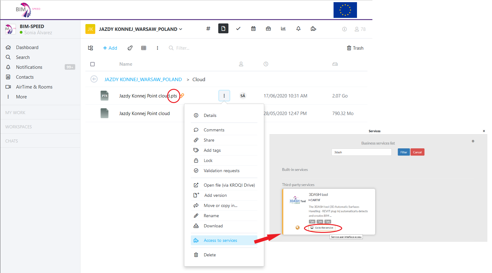
    The 3DASH Tool service is integrated into BIM-SPEED platform and accessible from there. The service is available in the platform if there is a point cloud available in .ptx, .pts or .pty format.

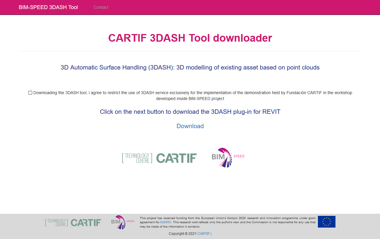
    After launch the 3DASH Tool service, and before to download the pug-in, the user must accept the terms and conditions of use of the tool in the GUI (Graphical User Interface).

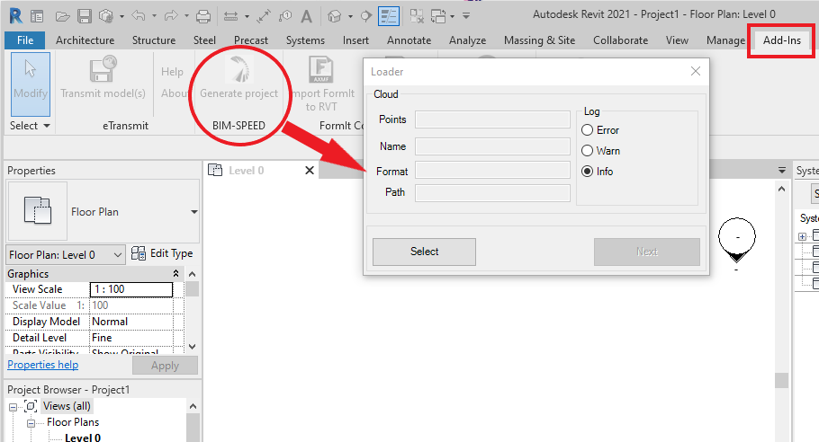
    Once the plugin is installed, from REVIT you can launch the tool and follow the instructions that will appear.


    Performance Requirement

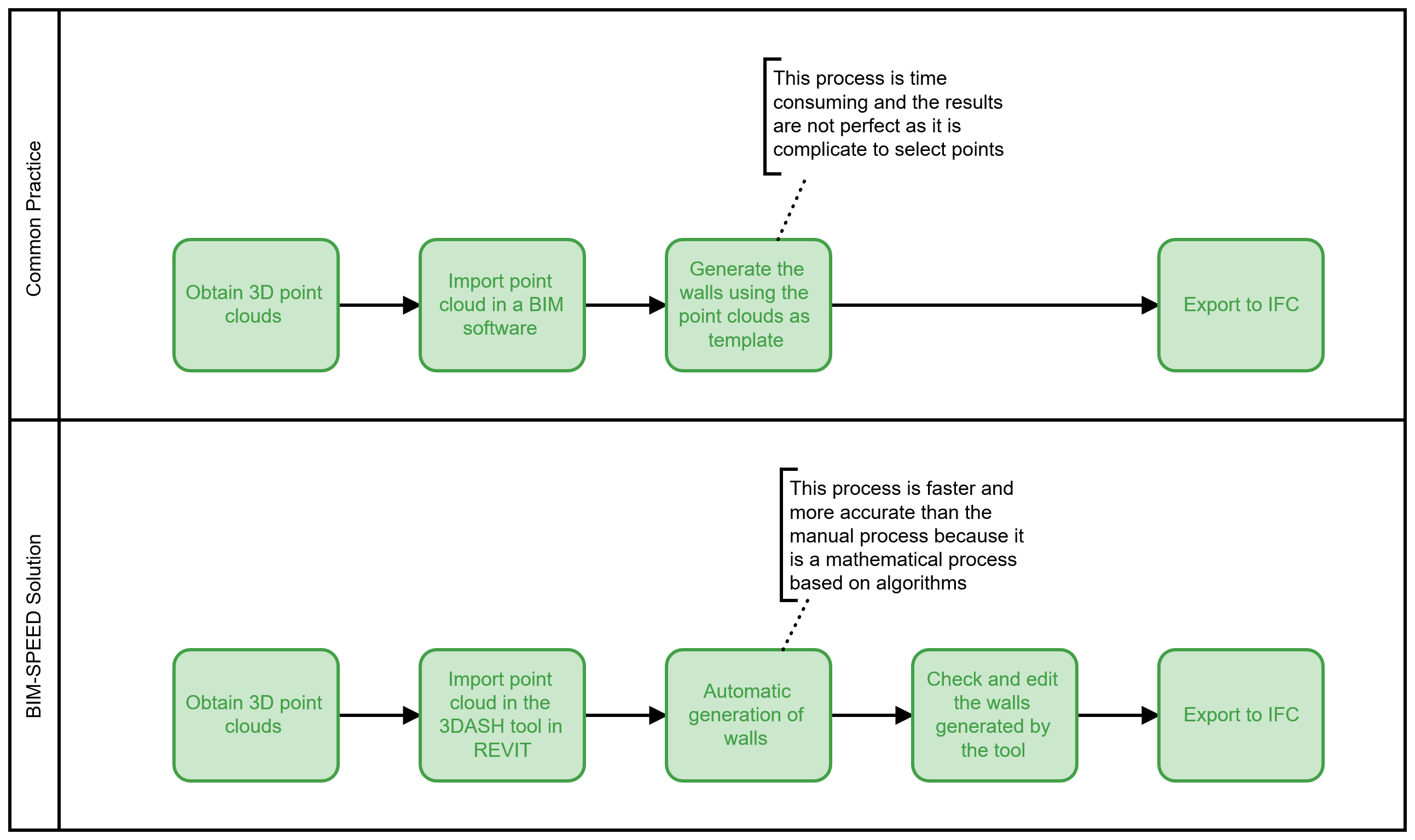
    The Scan to BIM method defines in this document allows to achieve a reduction of time in the generation of walls from point clouds, compare with the conventional practices. This process also improves the accuracy in the generation of walls from point clouds due to the fact it is a mathematical process based on algorithms. The image below shows this comparison with the conventional practices to obtain BIM models from Point Clouds.

    Images
    • 3DASH_GUI.png (png | 88.59 KB)
    • 3DASH_Revit.png (png | 46.90 KB)
    • 3DASH_service (1).png (png | 100.23 KB)
    • 3dash-bpmn-compare.png (png | 112.35 KB)