- Use cases
- Co-Creation Space
Community
Organizations
Collaboration Partners

- Login
NOT REGISTERED YET?
Register for the Use Case Management Service for free to start creating your first use case.
Registered users can use the download area and the comment functions.

All dokuments are licensed as a Creative Commons Attribution-NonCommercial-ShareAlike 4.0 International License
(Attribution-Non-Commercial-ShareAlike 4.0). Further information can be found at
![]()
The documents reflect the current best practice and do not claim to be complete. They should not to be understood in the sense of a generally valid recommendation or guideline from a legal point of view. The documents are intended to support appointing and appointed parties in the application of the BIM method. The documents must be adapted to the specific project requirements in each case. The examples listed do not claim to be complete. Its information is based on findings from practical experience and is accordingly to be understood as best practice and not universally applicable. Since we are in a phase in which definitions are only emerging, the publisher cannot guarantee the correctness of individual contents.
This document aims at describing the use case ‘Model Check for compliance testing and design coordination’, which is implemented as part of the BIM-SPEED EU Horizon 2020 project.
The aim of the BIM-SPEED project is to:
The general objectives of a model check are to ensure the following:
With regard to BIM-SPEED project, the specific aim is to ensure that 3D BIM models can be made accessible on the BIM-SPEED platform such that users have access to 3D BIM models that have already been verified.
The implementation of BIM has been carried out over several uses across life cycle of existing buildings in the BIM-SPEED Project. As the structures to be modelled are existing buildings, the 3D BIM models are modeled based on as-built documentation and enriched with information and data relevant for the renovation project.
To reach the aimed goals of a specific project, several BIM use cases will be performed. These BIM use cases require a 3D BIM model which is consistent to all requirements. The verification of this 3D BIM model needs to be assured to guarantee the interoperability for all needed BIM use cases.
The aim of this use case is, to ensure that the above requirements for the 3D BIM model are fulfilled by implementing and performing model checks. The outcome of these checks aids regional regulations and/or standards verification based compliance testing and ensures a well-defined model which captures accurate information for further geometrical checks for coordinated design and geometrical accuracy.

One of the main objectives of the BIM-SPEED project is to reduce the time of deep renovation projects by 30%. The implementation of model checks makes a major contribution to this, through automated and standardized model check processes, errors in the model can be detected at an early stage and efficiently corrected. Following picture shows the difference between the conventional way performing the checks and effort reduction by implementing automatic model checks. More details follow below.

Figure1: Comparison between conventional and BIM-SPEED approach to model checking
Rather obvious is the reduction of working time to perform the model checks.
Assuming to setup and define model checks for a 3D BIM model LoD (Level of Detail) 400 to 450 of a common residential building with 4 levels and approx. 300m² living space as reference, the time required cumulated is (based on experience):
The picture above highlights the inclusion of several manual process steps in the workflow of checking a 3D BIM model in conventional way, while the BIM-SPEED approach clearly outlines the consolidation of all these steps into a single automated process step. This accounts for impactful reduction in time, along with avoiding errors by providing standardized check templates. Furthermore, the possibility to export issues as BCF files, directs the BIM author directly to each issue within his own CAD or viewer software, which enhances the process of verification by avoiding communication errors.
In the course of the model checks,
Combining both types of model checks in the end will assure compliance to national/ regional specific/ other standards and verify ranges along with naming/semantic/other informational requirements for further BIM uses. One main focus is, to ascertain the handover to geometrical verification procedures, like clash detection and/or deviation analysis. These aids avoiding errors in geometrical accuracies and saving costs and time by identifying clashes of different disciplines already in project execution stages.
Advantages
Standardizing Model Requirements, country-specific features excluded, as basis for the 3D BIM Model generation, will allow to develop a generalized workflow for verifying 3D BIM models in terms of geometry and provided information within the model elements, which can be applied to different models and different projects.
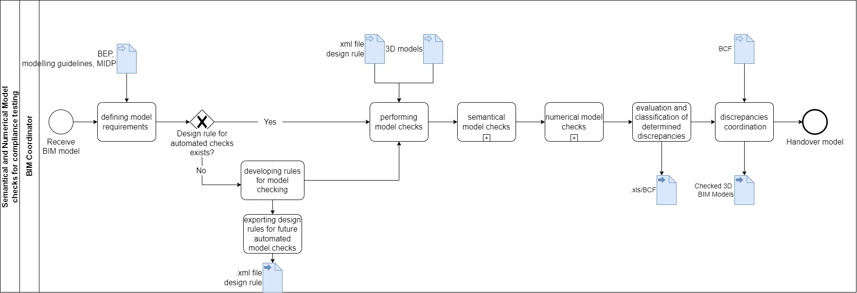
Figure 7: Illustration of file format requirements for implementation of UC
The process map above highlights the input, output data and file exchange possibilities throughout the process of the defined model checks. For the execution of the UC,
The basic process of a model check is not changed within the scope of the BIM-SPEED project, it is only adapted based on the BIM-SPEED specific requirements.
In order to illustrate the importance of the individual model checks for the design coordination process, an overview is given in the following process map. The complete design coordination process requires further approval (e.g. also approval of the 2D Drawings, etc.) but this pictures shows the part of the process to assure an approved 3D BIM model to be handed over for further coordination tasks within the complete process.
The process of the individual model checks is explained in more detail in further sections

Figure2: Extract of Design Coordination Process
In the general process, the BIM author generates the 3D BIM model including other information and design related requirements coming from project standards like BEP, Modelling Guidelines and MIDP and generates the corresponding required 2D Drawings out of it. Upon creating the 3D BIM model, this is handed over to the BIM coordinator who carries out numerical and semantical checks based on the model requirements. Upon carrying out these checks, the discrepancies are realized, classified and shared with the BIM author who then has to update the 3D BIM model accordingly.
The following process map gives breakdown of the specific process steps for semantical and numerical model checks.

Figure 3: Semantical and Numerical model checks process
The process of semantical and numerical checks consists of initially defining model requirements which forms the basis for the process of model checking. Within the scope of BIM-SPEED Project automated checks have been implemented to reduce the time required for carrying out these checks. Upon identification of design rules, the existence of pre-defined templates for these design rules is checked. If this exists, such rule is imported to carry out automated checking of the 3D BIM Model. If such pre-defined automated rule does not exist, it has to be developed (the process can be referred to the section of demonstration case).
Semantical Check
Semantical model checks verify the consistence of the elements. Therefore, each model element is checked regarding its nature, because only elements that are created as 3D volumes can processed smoothly in further activities. For example, 2D elements can lead to miscalculation in quantity take off or in energy calculations and may be ignored, when performing a clash detection. Semantical model checks approve whether the properties assigned to a model element match the corresponding naming convention. Compliance with naming convention is a pre-requisite for a 3D BIM model, particularly automated model checking to be evaluable by software solutions for further BIM use cases. The naming convention needs to be defined at the beginning of each project.
Numerical Check
The existence and compliance of all needed properties are already verified by the semantical checks. Following on this, the numerical checks verify the values of all properties for each element, regarding project specific requirements and accordance to predefined, selectable or calculated values.
Discrepancies resulting from semantical and numerical model checks, are classified and reported to the BIM author to be corrected and verified. Report format in this case is the BCF format, which allows automated guidance to relevant issues within the authoring software.
The following section gives a demonstration of the operation process described in the process map and its results.
Demonstration Case
The ‘Vitoria demonstration site’ in Spain, is a residential building located in the city of Vitoria-Gasteiz. Several design rules have been identified such as country specific standards and project specific requirements. A list of mandatory properties has been collected (attached) and translated to single xml files, to be imported while carrying out these checks. A total of 59 semantical and numerical checks were derived which can also deal as templates and can be enhanced based on requirements.
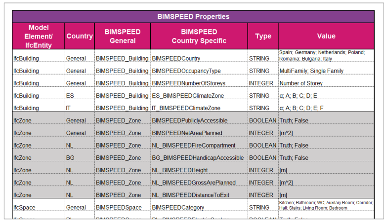
The table above gives a glimpse to some properties defined from which design rules and checking criteria are derived.
Following an example workflow to define model checks based on existing design rules:
One textual design rule for a Spanish Construction project, identified within this project says:
“In Spain in climate zone A-E, each external wall needs to have an acoustic rating of more than 35dB”
This textual design rule now is translated to a logical syntax, as shown in the image below. Doing this enables to identify required Entities and Properties to set ab the script based model check.

This rule can be explained in words as:
If there is a geometry model of a building, then there will be an entity “IfcBuilding”. When there is an entity “Ifc Building” and the general attribute “BIMSPEEDCountry” provides the value “Spain” as well as the country specific attribute “ES_BIMSPEEDClimateZone” provides one of the values “a, A, B, C, D or E”, AND if the entity IfcWall can by identified as external wall using the attribute “BIMSPEEDIsExternal” providing the value “True”, then this entity of “IfcWall” must have the attribute “BIMSPEEDAcousticRating” with a value bigger than 35,00db.
This is translated to the code (as shown below) and exported as an xml file for automated checks:
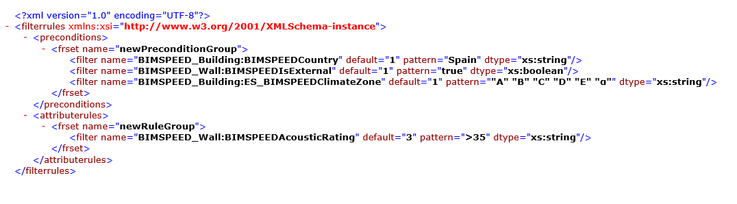
Figure 4: XML Script for defining the model check within the model checking software
Importing the corresponding 3D BIM Model and this model check rule as xml file now into the model checking software, will enable to perform the model check.
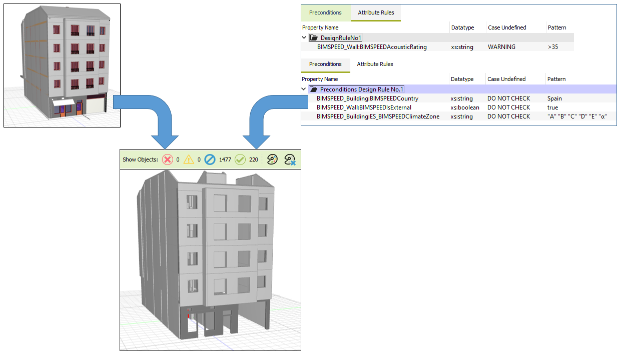
Figure 5: Evaluation of properties with regard to their numerical correctness
Results acquired from demonstration site:
The semantical and numerical checks carried out, that the 3D BIM model does not comply with the guidelines. The checks have identified 142 model elements, that are in fact walls, but they do not provide the required parameter BIMSpeedAcousticRating, which each model element should contain to enable the usage in the aimed BIM use cases.

NOT COMPLY: Property BIMSPEEDAcouticRating is missing in Pset IfcWall
Completing interpreting the identified results, there luckily have been 220 model elements identified, that are in compliance with these requirements.

COMPLY: Property BIMSPEEDAcouticRating is provided in Pset IfcWall
Figure 6: Results from checks performed on 3D BIM Models
Beside the complying and not complying model elements, the performed model check also outlines, that there have been 1332 elements ignored for this specific check (see screenshot, marked in blue). These elements have not been checked at all, as in the definition of the check, there has been set a precondition to only check elements that are identified as ifcWall. All other elements can be ignored and don’t need to be checked, to keep the performance within the model checking software fluid.
Model checks, within the scope of this UC, namely semantical and numerical checks are relevant pre-requisites for several BIM use cases. Semantical checks provide the security that all relevant information is defined and integrates information in a well-defined manner. While semantical checks verify the existence and definition of all relevant IFC properties semantically, the numerical checks validate the values of properties for each element. Furthermore, automated quality checks as developed within this UC, further enhances saving of time. Both these checks also ensure that the compliance of regional regulations and standards are captured within the 3D BIM model and its relevant model elements.
The feasibility of implementation of this use case depends on the extent of automation of semantical and numerical model checks.
The aim of this use case is to improve the process of model checking by making the process faster and less error-prone. In cases where feasibility of automating checks does not prove feasible, the user of this UC is benefited from support related to independently implement semantical and numerical model checks for compliance testing and design coordination.
The model checks defined within the UC are the pre-requisites for ensuring coordination amongst design models in terms of semantical and numerical correctness. This forms the pre-requisite for carrying out further geometrical checks like clash detection, where the coordination between various design models are verified. A clash detection can only be followed correctly upon having semantically and numerically verified design models. This has also been indicated in the Overall process map in the previous section.
Semantical Checks:
To perform semantical checks, the following aspects need to be taken into account:
Numerical Checks:
To perform numerical checks, the following aspects need to be taken into account: