UCM buildingSMART International Logo
  • Keine Ergebnisse gefunden
  • Anwendungsfälle
  • Co-Creation Space
  • Community
    • buildingSMART
      • buildingSMART International
      • buildingSMART Österreich
      • buildingSMART Benelux
      • buildingSMART Deutschland
      • buildingSMART Schweiz
    • Organisationen
      • HSLU
    • Kooperationspartner
      • Unternehmen
      • Verbände & Institutionen
      • Experten
  • de
    • en
    • de
    • fr
  • Anmelden
Standort
buildingSMART Schweiz Andreasstrasse 5 8050 Zürich (Schweiz)ucm@buildingsmart.ch
Unternehmen
StartseiteÜber unsCommunitySchulung
Ressourcen
AnwendungsfälleCo-Creation SpaceVersionshinweiseFAQ
buildingSMART Logo
Copyright © 2025 buildingSMART. Alle Rechte vorbehalten.
KontaktDatenschutz- und Cookie-ErklärungAllgemeine Geschäftsbedingungen
Small IconAI Chat

    Rear-ventilated cladding for exterior walls

    Kommentare

    Kommentare werden geladen...

    NOCH NICHT REGISTRIERT?


    Registrieren Sie sich für den Use Case Management Service kostenlos, um Ihren ersten Use Case zu erstellen.


    Registrierte Benutzer können den Download-Bereich und die Kommentarfunktionen nutzen.

    Rear-ventilated cladding for exterior walls
    Dokumenttyp
    Anwendungsfall
    GUID
    0C893CC1-5BB5-47EB-8F04-B926036B67C8
    Kennung
    CHE.5311.04.02
    Lebenszyklusphase
    SIA 112
    Revision
    V1.1.0
    Projektstatus
    Genehmigt
    Reifegrad
    Beispiel
    Veröffentlicht am
    30. Nov. 2024
    Letzte Änderung
    22. Jan. 2025
    Herausgeber
    buildingSMART Switzerland
    Autoren
    • Philippe Willareth
    • Remo Kunz
    Startseite
    Anwendungsfälle
    Rear-ventilated cladding for exterior walls

    Anwendungsfall Dokumentdefinition

    Austauschanforderungen

    IFC/IDS

    Impressum

    Architectural model preliminary project
    • Architectural model of the building envelope – LOG 100 – preliminary project
    • IDS for model verification

    IFC Version

    IFC 4.3 ADD2 (4.3.2.0)IFC 4.3 ADD2 (4.3.2.0)

    IFC Datei

    IDS Version

    V1.0V1.0

    IDS Datei

    Architectural model construction project
    • Architectural model of the building envelope – LOG 200 – construction project
    • IDS for model verification

    IFC Version

    IFC 4.3 ADD2 (4.3.2.0)IFC 4.3 ADD2 (4.3.2.0)

    IFC Datei

    IDS Version

    V1.0V1.0

    IDS Datei

    Projektgruppe

    • Ban David Mate (FUTURE MATERIALS GmbH)
    • Michael Drobnik (Herzog & de Meuron)
    • Remo Kunz (gkp fassadentechnik ag)
    • Gebäudehülle Schweiz Rauber (Verband Gebäudehülle Schweiz)
    • Goeddertz Stefan (Herzog & de Meuron)
    • Ljupco Stoilov (Implenia Schweiz AG)
    • Joel Studer (Ecolite AG)
    • Philippe Willareth (Lüchinger+Meyer)

    Partner

    Urheberrecht

    All documents are licensed as a Creative Commons Attribution-NonCommercial-ShareAlike 4.0 International License
    (Attribution-Non-Commercial-ShareAlike 4.0). Further information can be found at

    creativecommons

    Handhabung

    The documents reflect the current best practice and do not claim to be complete. They should not to be understood in the sense of a generally valid recommendation or guideline from a legal point of view. The documents are intended to support appointing and appointed parties in the application of the BIM method. The documents must be adapted to the specific project requirements in each case. The examples listed do not claim to be complete. Its information is based on findings from practical experience and is accordingly to be understood as best practice and not universally applicable. Since we are in a phase in which definitions are only emerging, the publisher cannot guarantee the correctness of individual contents.

    • CHE-5311-04-02_Ifc4x3_LOG100.ifc (ifc | 790,08 KB)
    • CHE-5311-04-02_Ifc4x3_BimQ_IDS.ids (ids | 17,04 KB)
    • CHE-5311-04-02_Ifc4x3_LOG200.ifc (ifc | 19,35 MB)
    • CHE-5311-04-02_Ifc4x3_BimQ_IDS.ids (ids | 17,04 KB)

    Beschreibung

    The ventilated cladding of exterior walls, including thermal insulation and connections, ensures that the basic building physics requirements for meeting the energy certificate, including summer and winter heat and moisture protection, are met. Due to the pronounced system and functional separation and the generally small construction mass, the construction method is characterized by high C02-eq and circularity efficiency. The method is suitable as a sustainable construction method for both renovations and new buildings.

    The following applies to the rear-ventilated cladding of external walls (vertically mounted and rear-ventilated boundary of the building envelope): externally positioned and rear-ventilated cladding of external walls, including thermal insulation and interfaces with connecting components such as glazing, roof edges, flooring surfaces or supporting structure elements.

    The main layers consist of supporting structure elements such as columns, joists, walls (shell construction, or mounting base for facade anchoring), substructure, insulation layer and exterior cladding. Each of the layers fulfills defined functions such as weather protection, thermal insulation, airtightness, load transfer, etc. and must be coordinated holistically. The minimum performance requirements are the fulfillment of the energy certificate including summer and winter heat and moisture protection. The performance requirements can be supplemented on a project-specific basis, for example with fire protection requirements, etc.

    The multi-layer structure should be assigned information for the project planning and as a basis for the tendering as a complete component “rear-ventilated cladding of external walls”. This information usually includes the phase-specific technical specifications and the geometric information with a low level of detail (LOG 200-300) for generating the quantity takeoffs (cost estimate / cost projection).

    The use case defines a collaboration between architecture and facade planning (ARCH synergy model) that focuses on synergies. The facade planning is assigned to the architecture with regard to the BIM processing. The facade engineering services are assigned to the architectural facade BIM model by means of specifications or attributes. Thus, the use case primarily defines the collaboration and the requirements for the ARCH model and explicitly the requirements for the statements to be generated from the model.

    Minimal specifications or typical attributes are:

    • Definition of component groups and construction types (basis for the BIM-generated bill of materials for cost estimate / cost projection and bill of quantities)
    • Specifications of U-values, line allowances, etc. (basis for energy certificates and assessment of thermal comfort)

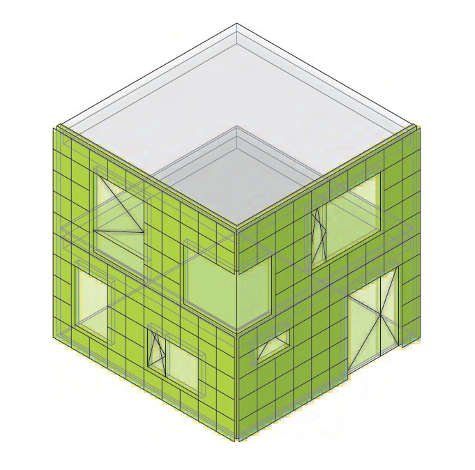
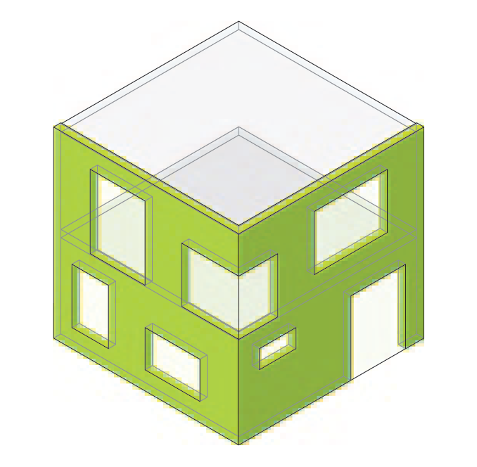
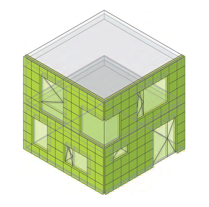
    Geometrically, the ARCH model, with a targeted low LOG, is based on the architectural planning and the technical details or layer plans developed by the facade engineering.

    Lieferleistung

    • Consistent information management
    • Increased efficiency in processing and collaboration
    • Increased cost accuracy due to BIM-generated mass statements
    • Conceptual description of the interface between architecture and facade planning (handling of different LOG requirements)
    • Representation of the facade in the ARCH model
    • Minimal geometric modeling (low LOG level) that allows coordination with the structural design
    • Adequate information of the ARCH model (medium level of information need) for content coordination and the respective project-specific parameters, e.g. burglary class, CO2 footprint, etc., between architecture, building physics, structural engineering, fire protection and facade planning.

    Lebenszyklusphasen

    SIA 112

    BIM-Ziele & Vorteile

    • Preliminary project: Generate bill of quantities for cost estimate (CO) in m2 and running meters Interfaces, for running meters, define where measurements are taken (inside, axis, outside)
    • Construction project: Generate bill of quantities for cost estimate (CO) in m2, running meters Interfaces and quantities
    • Define exterior-facing and back-ventilated cladding of exterior walls incl. thermal insulation
    • Interfaces to connecting components such as glazing, roof edges, flooring surfaces or supporting structure elements.
    • Modeling of sealing, landscaping, opening elements (accessibility, windows, sun/glare protection, fire protection concept, heating, ventilation, air conditioning and sanitation), etc.
    • Determining the fastening technology
    • Modeling guidelines for correct execution in the construction project


    Abgrenzung

    • The use case focuses on the project planning phases, including the basics for the submission. In explicit deviation from the building envelope use case, the current use case avoids double modeling of architecture (ARCH) and facade models. Accordingly, with regard to facade planning, we speak of an ARCH synergy model.
    • The use case only includes the presentation of the digital input and its implementation as a level of information need, i.e. who does what, who when, what and how (level of detail) when applying the BIM method.
    • All topics related to the scope of services and thus to contractual and fee-related issues are explicitly excluded.
    • All services described by all parties must be specifically agreed as of today.
    • The implementation phases are not part of the use case
    • Lightning protection, electrical and HVAC planning only take place in the implementation phase
    • Photovoltaics (PV) are treated in the same way as a facade element
    • The substrate is always a load-bearing element (concrete, wood, etc.)
    • Cantilevered facade elements are not considered, but the architectural design of the facade cladding (design) must be taken into account.
    • Contractual and fee-related services must be agreed in writing in advance between the parties.

    Standards / Referenzdokumente

    • Level of Information Need: Basics
    • Level of information need: building construction – application
      Application in building construction on the base of SN EN 17412-1 Building information modelling – Level of information need – Part 1, Concepts and principles.
    • SIA 118/232:2011
      General conditions for sloping roofs and rear-ventilated cladding on external walls – Contractual conditions for the SIA 232/1:2011 and 232/2:2011 standards
    • SIA 118:2013
      General terms and conditions for construction works
    • SIA 232/1:2013
      Sloping roofs – Corrigendum C1 to the SIA 232/1:2011
    • SIA 232/2:2011
      Rear-ventilated cladding of external walls
    • SZFF 12.01 Edition 2024
      Prestations de planification dans la construction de façades Concepteur/trice de façades ou ingénieur/e en façades
    • SZFF 13.01
      Tender, offer and execution of windows, facades and metal construction work (supplement to SIA 118)

    Abkürzungen

    • AM Suisse - Dachverband für die Fachverbände Agrotec Suisse und Metaltec Suisse
    • ARCH model – architecture model
    • GWP - Global Warming Potential
    • LCA - Life-Cycle-Assessment
    • LOG - Level of Geometrie
    • LOI - Level of Information
    • SIA - swiss socity of engineers and architects / DE: Schweizerische Ingenieur- und Architektenverein
    • SFHF - Schweizerischer Fachverband für hinterlüftete Fassaden
    • SZFF - Schweizerische Zentrale Fenster und Fassaden

    Dateien

    https://bauen-digital.ch/publikationen/
    https://bauen-digital.ch/publikationen/
    • er_rear-ventilated cladding for exterior walls_EN_V1.2.0.xlsx (xlsx | 13,10 KB)

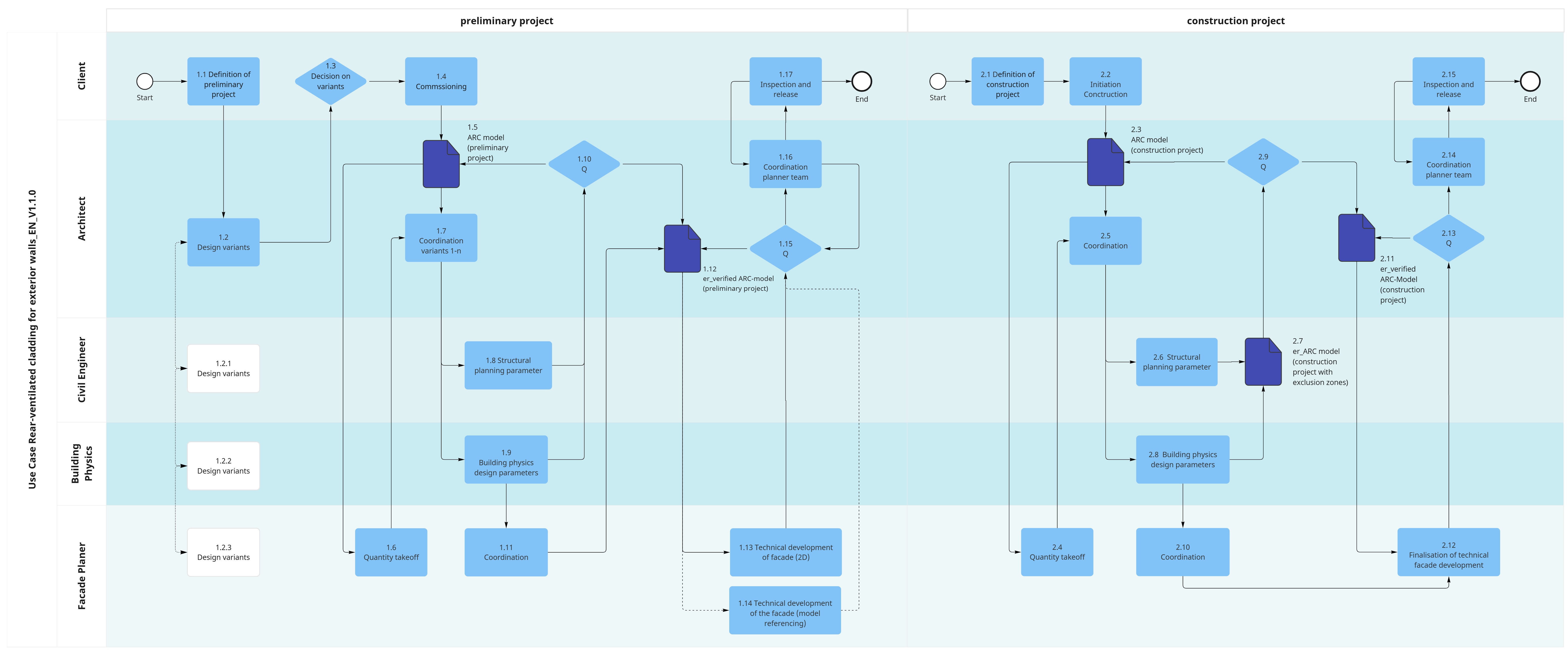
    Process

    Prozessdiagramm

    Gesamtprozess

    Beschreibung

    Dateien
    • pm_rear-ventilated cladding for exterior walls_EN_V1.1.0.pdf (pdf | 85,95 KB)

    SIA 112

    31 | Concept Design
    1.1 | Definition of preliminary project objectives
    1.2 | Design variants
    1.3 | Decision on variants
    1.4 | Commissioning
    1.5 | er_ARC model (preliminary project)
    1.6 | Quantity takeoff
    1.7 | Coordination variants 1-n
    1.8 | Structural planning parameters
    1.9 | Building physics design parameters
    1.10 | Quality check
    1.11 | Coordination
    1.12 | er_Verified ARC-Model (preliminary project)
    1.13 | Technical development of facade (2D)
    1.14 | Technical development of the facade (model referencing)
    1.15 | Quality check
    1.16 | Coordination planning team
    1.17 | Inspection and release
    32 | Detail Design
    2.1 | Definition of construction project objectives
    2.2 | Initiation Conctruction Phase
    2.3 | er_ARC model (construction project)
    2.4 | Quantity takeoff
    2.5 | Coordination
    2.6 | Structural planning parameters
    2.7 | er_ARC model (construction project with exclusion zones)
    2.8 | Building physics design parameters
    2.9 | Quality check
    2.10 | Coordination
    2.11 | er_Verified ARC-Model (construction project)
    2.12 | Finalisation of technical facade development
    2.13 | Quality Check
    2.14 | Coordination planning team
    2.15 | Inspection and release

    Define the objectives of the preliminary project:

    • cost planning and cost optimisation
    • input labels (GWP) based on area division and types

    Initiator: Client

    The architect draws up various options and discusses them with the specialist planners.

    • 1.2.1 Construction options for the civil engineer
    • 1.2.2 Construction options for the building physicist
    • 1.2.3 Construction options for the facade planner

    Initiator: Architect

    The client reviews the various options and approves the options to be developed. The decision on the options is made on the basis of drawings/sketches, reference projects and evaluated using a matrix. This includes, among other things, benchmark figures for CO2, GWP, etc.

    Initiator: Client

    The client defines the type of commission, e.g. individual commission, general planning, etc.

    Initiator: Client

    LOG 100

    • Basic design and openings schematic

    LOI 200

    Generic requirements

    • Building location
    • Quantities / volumes (base quantities) as a base for cost estimate / cost projection and GWP calculation
    • Typification of facade element
    • Total area of windows (transparent surfaces), doors, wall structures (assignable surfaces)

    Project-specific requirements – not included in the Information Delivery Specification (IDS)

    • Fire protection requirements – in consultation with the Swiss Cantonal Fire Insurers Associatio

    Note:

    • CO2 equivalents for Global Warming Potential (GWP) are taken from the environmental product declarations (EPDs) and are not included in the model. The GWP calculation is carried out using the corresponding tools

    Initiator: Architect

    Executer: Civil Engineer

    Export of quantities with corresponding parameters
    Extension with project-specific requirements (e.g. fire protection)

    Initiator: Facade Planner

    The architect coordinates the options chosen by the client together with the specialist planners.

    Initiator: Architect

    Specification of mounting surface and deflections. Document in planning concept without information from model. 

    Initiator: Civil Engineer

    The building physics planning parameters are coordinated and created with all the planners required for the specific project.

    Examples:

    • Energy certificate and definition of u-values and g-values, shading requirements, max. glass proportion
    • Sound insulation specifications
    • Sealing requirements

    Note:

    • This use case does not include project-specific data, which must be added individually.

    Initiator: Building Physics

    • Check whether all the necessary specifications are available and whether the requirements (e.g. building regulations and project-specific requirements of the client) are fulfilled.

    Initiator: Architect

    • Technical coordination of all aspects

    Initiator: Facade Planner

    Enhancement of the model with geometrically coordinated bases and specifications for material qualities (materialisation)

    LOG 100
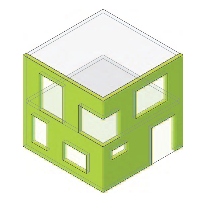
    • Load-bearing structure, floor slabs, wall structures, window, openings

    LOI 200

    • material specifications

    Initiator: Architect

    Executer: Facade Planner

    • Design development incl. requirements for rear ventilation, fire protection, etc.
    • 2D documentation without model referencing
    • Checks variants 1-n

    Documentation delivery:

    • Guiding details book / 2D sections (pdf)
    • Usage agreement
    • Cost estimimation
    • Technical report

    Note:

    • In general, work in this step is still done in 2D. It is also possible to continue working in the ARC models.

    Initiator: Facade Planner

    • same as1.10 including referencing of the sections in the model

    Note:

    • This step is optional and represents an additional service.

    Initiator: Facade Planner

    • Check whether all the necessary specifications are available and whether the requirements (e.g. building regulations and project-specific requirements of the client) are fulfilled.

    Initiator: Architect

    Performance coordination

    • Geometrically coordinated model
    • Technical coordination documented
    • Consolidated and coordinated phase completion


    Initiator: Architect

    • Review of the results and approval for the next project phase

    Initiator: Client

    Define the objectives of the construction project:

    • cost planning and cost optimisation
    • input labels (GWP) based on area division and types

    Initiator: Client

    Client approves the initation of the construction phase

    Initiator: Client

    The ARC model must be detailed in accordance with the requirements.

    The level of detail of the model and the information provided must be sufficient for the preparation of the tender / tender planning.

    Note:

    • Depending on the type of project, it may also be possible to work with different technical models (e.g. ARC; structure; etc.) at this point. This use case represents the simplest variant.

    LOG 200

    • Load-bearing structure, ceiling structures, wall structures, sealing, landscaping, opening elements (accessibility, windows, sun/glare protection, fire protection concept, heating, ventilation, air conditioning, plumbing), etc.
    • Referencing of key details (optional)

    LOI 200

    LOI 200

    • building location
    • base quantities as a base for cost estimate / cost projection and GWP calculation
    • typification of facade element
    • total area of windows (transparent areas), doors, wall structures (assignable areas)
    • fire protection specifications
    • material specifications
    • grid with format specifications
    • running metres interfaces to doors, windows, roof edge, base, balcony.
    • quantities - built-in parts

    Note:

    • CO2 equivalents for Global Warming Potential (GWP) are taken from the environmental product declarations (EPDs) and are not available in the model. The GWP calculation is carried out using the appropriate tools

    Initiator: Architect

    Executer: Civil Engineer

    • Export of quantities with corresponding parameters
    • Extension with project-specific requirements (e.g. fire protection)

    Initiator: Facade Planner

    •  The architect coordinates the options chosen by the client together with the specialist planners.

    Initiator: Architect

    • Specification of mounting surface, deflections and movements (earthquakes)
    • Document in the planning concept without information from the model

    Initiator: Civil Engineer

    • Corresponds to ARC model (construction project) with additional modelling of exclusion zones

    Initiator: Civil Engineer

    Executer: Architect

    The building physics planning parameters are coordinated and created with all the planners required for the specific project, such as fire protection, burglary, LCA, etc.

    Examples:

    • Confirmation of energy certificate
    • Definition of u-values
    • Shading requirements
    • Definition of sound insulation
    • Definition of air permeability

    Initiator: Civil Engineer

    • Check whether all the necessary specifications are available and whether the requirements (e.g. building regulations and project-specific requirements of the client) are fulfilled.

    Initiator: Architect

    • Technical coordination of all aspects

    Initiator: Architect

    • Enhancement Model with geometrically coordinated foundations and specifications
    • Material qualities (materialisation)

    LOG 200

    • Load-bearing structure, floor slabs, wall structures, window, openings

    LOI 200

    • Total area Windows (transparent surfaces), doors, wall structures (surface areas that can be occupied)
    • Fire protection requirements
    • Type of cladding / cladding material
    • Material specifications
    • Grid with format specifications
    • Running metres Interfaces to doors, windows, roof edge, base, balcony, etc.

    Initiator: Architect

    Executer: Facade Planner

    • Design development
    • 2D documentation with model referencing
    • Checks variants of selected designs


    Documentation provided:

    • Key details book / 2D sections (pdf)
    • Usage agreement
    • Quotation
    • Global Warming Potential (GWP)
    • Grey energy
    • Technical report

    Initiator: Facade Planner

    • Check whether all the necessary specifications are available and whether the requirements (e.g. building regulations and project-specific requirements of the client) are fulfilled.

    Initiator: Architect

    Performance coordination

    • Geometrically coordinated model
    • Technical coordination documented
    • Consolidated and coordinated phase completion

    Decision

    • Ready for tender

    Initiator: Architect

    • Check whether the model is ready for the tendering phase.
    • Client approves next project  phase. 

    Initiator: Client