- Aucun résultat trouvé
- Cas d'utilisation
- Co-Creation Space
Communauté
Organisations
Partenaires de collaboration
- Connexion
PAS ENCORE INSCRIT?
Inscrivez-vous au Service de Gestion des Cas d'Utilisation gratuitement pour commencer à créer votre premier cas d'utilisation.
Les utilisateurs inscrits peuvent utiliser la zone de téléchargement et les fonctions de commentaire.


All documents are licensed as a Creative Commons Attribution-NonCommercial-ShareAlike 4.0 International License
(Attribution-Non-Commercial-ShareAlike 4.0). Further information can be found at
![]()
The documents reflect the current best practice and do not claim to be complete. They should not to be understood in the sense of a generally valid recommendation or guideline from a legal point of view. The documents are intended to support appointing and appointed parties in the application of the BIM method. The documents must be adapted to the specific project requirements in each case. The examples listed do not claim to be complete. Its information is based on findings from practical experience and is accordingly to be understood as best practice and not universally applicable. Since we are in a phase in which definitions are only emerging, the publisher cannot guarantee the correctness of individual contents.

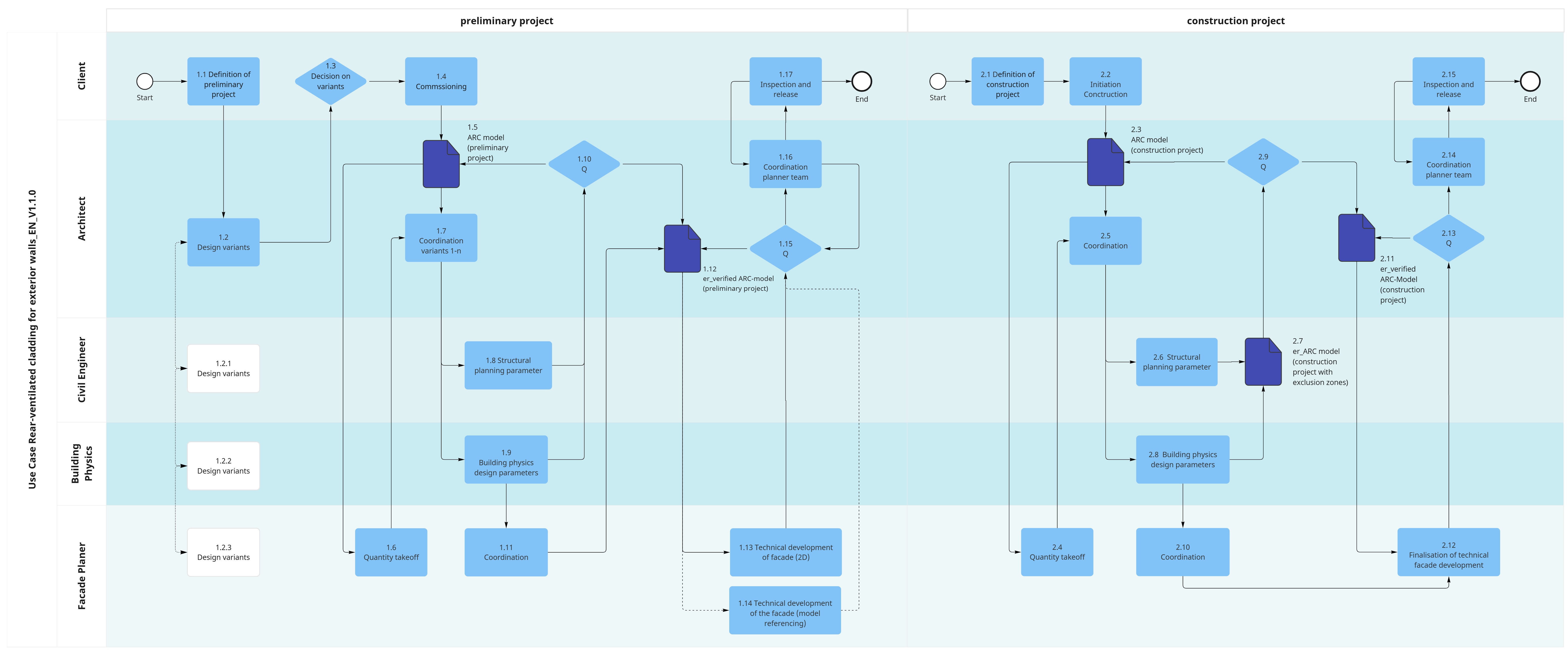
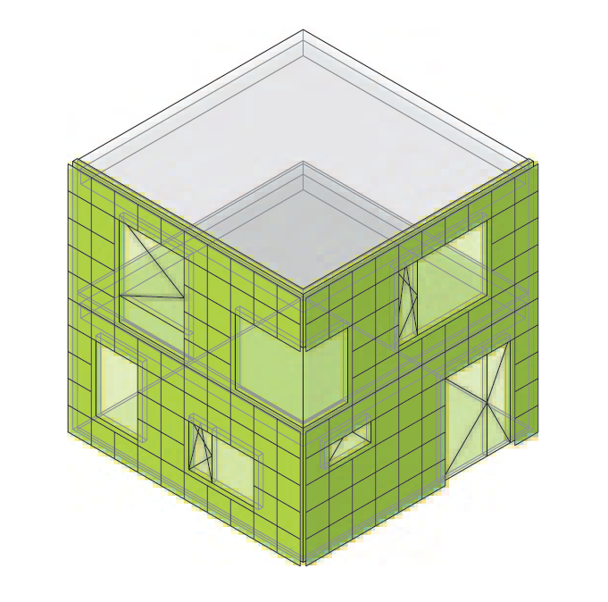
The ventilated cladding of exterior walls, including thermal insulation and connections, ensures that the basic building physics requirements for meeting the energy certificate, including summer and winter heat and moisture protection, are met. Due to the pronounced system and functional separation and the generally small construction mass, the construction method is characterized by high C02-eq and circularity efficiency. The method is suitable as a sustainable construction method for both renovations and new buildings.
The following applies to the rear-ventilated cladding of external walls (vertically mounted and rear-ventilated boundary of the building envelope): externally positioned and rear-ventilated cladding of external walls, including thermal insulation and interfaces with connecting components such as glazing, roof edges, flooring surfaces or supporting structure elements.
The main layers consist of supporting structure elements such as columns, joists, walls (shell construction, or mounting base for facade anchoring), substructure, insulation layer and exterior cladding. Each of the layers fulfills defined functions such as weather protection, thermal insulation, airtightness, load transfer, etc. and must be coordinated holistically. The minimum performance requirements are the fulfillment of the energy certificate including summer and winter heat and moisture protection. The performance requirements can be supplemented on a project-specific basis, for example with fire protection requirements, etc.
The multi-layer structure should be assigned information for the project planning and as a basis for the tendering as a complete component “rear-ventilated cladding of external walls”. This information usually includes the phase-specific technical specifications and the geometric information with a low level of detail (LOG 200-300) for generating the quantity takeoffs (cost estimate / cost projection).
The use case defines a collaboration between architecture and facade planning (ARCH synergy model) that focuses on synergies. The facade planning is assigned to the architecture with regard to the BIM processing. The facade engineering services are assigned to the architectural facade BIM model by means of specifications or attributes. Thus, the use case primarily defines the collaboration and the requirements for the ARCH model and explicitly the requirements for the statements to be generated from the model.
Minimal specifications or typical attributes are:
Geometrically, the ARCH model, with a targeted low LOG, is based on the architectural planning and the technical details or layer plans developed by the facade engineering.

Specification of mounting surface and deflections. Document in planning concept without information from model.
Initiator: Civil Engineer
The building physics planning parameters are coordinated and created with all the planners required for the specific project.
Examples:
Note:
Initiator: Building Physics
Initiator: Architect
Initiator: Facade Planner
Enhancement of the model with geometrically coordinated bases and specifications for material qualities (materialisation)
LOG 100
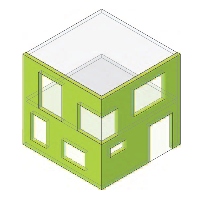
LOI 200
Initiator: Architect
Executer: Facade Planner
Documentation delivery:
Note:
Initiator: Facade Planner
Note:
Initiator: Facade Planner
Initiator: Architect
Performance coordination
Initiator: Architect
Initiator: Client
Initiator: Civil Engineer
Executer: Architect
The building physics planning parameters are coordinated and created with all the planners required for the specific project, such as fire protection, burglary, LCA, etc.
Examples:
Initiator: Civil Engineer
Initiator: Architect
Initiator: Architect
LOG 200
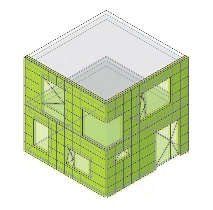
LOI 200
Initiator: Architect
Executer: Facade Planner
Documentation provided:
Initiator: Facade Planner
Initiator: Architect
Performance coordination
Decision
Initiator: Architect
Initiator: Client
Define the objectives of the preliminary project:
Initiator: Client
The architect draws up various options and discusses them with the specialist planners.
Initiator: Architect
The client reviews the various options and approves the options to be developed. The decision on the options is made on the basis of drawings/sketches, reference projects and evaluated using a matrix. This includes, among other things, benchmark figures for CO2, GWP, etc.
Initiator: Client
The client defines the type of commission, e.g. individual commission, general planning, etc.
Initiator: Client
LOG 100
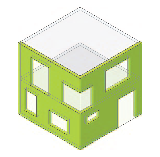
LOI 200
Generic requirements
Project-specific requirements – not included in the Information Delivery Specification (IDS)
Note:
Initiator: Architect
Executer: Civil Engineer
Export of quantities with corresponding parameters
Extension with project-specific requirements (e.g. fire protection)
Initiator: Facade Planner
Define the objectives of the construction project:
Initiator: Client
Client approves the initation of the construction phase
Initiator: Client
The ARC model must be detailed in accordance with the requirements.
The level of detail of the model and the information provided must be sufficient for the preparation of the tender / tender planning.
Note:
LOG 200
LOI 200
LOI 200
Note:
Initiator: Architect
Executer: Civil Engineer
Initiator: Facade Planner
Initiator: Architect
Initiator: Civil Engineer
The architect coordinates the options chosen by the client together with the specialist planners.
Initiator: Architect