- Use cases
- Co-Creation Space
Community
Organizations
Collaboration Partners

- Login
NOT REGISTERED YET?
Register for the Use Case Management Service for free to start creating your first use case.
Registered users can use the download area and the comment functions.

All dokuments are licensed as a Creative Commons Attribution-NonCommercial-ShareAlike 4.0 International License
(Attribution-Non-Commercial-ShareAlike 4.0). Further information can be found at
![]()
The documents reflect the current best practice and do not claim to be complete. They should not to be understood in the sense of a generally valid recommendation or guideline from a legal point of view. The documents are intended to support appointing and appointed parties in the application of the BIM method. The documents must be adapted to the specific project requirements in each case. The examples listed do not claim to be complete. Its information is based on findings from practical experience and is accordingly to be understood as best practice and not universally applicable. Since we are in a phase in which definitions are only emerging, the publisher cannot guarantee the correctness of individual contents.
The semantic design rules are developed to represent the denotation of elements and the relationships between these elements. Under the scope of BIM-SPEED project, semantics are useful to ‘translate’ experts’ knowledge about buildings regulations into a language that can be understandable by data experts. Once this knowledge is translated to a computer-based language, the rules are accommodated to the model checker tool, where an automatic regulation compliance checking is performed. The purpose of the checking process is to warn the users for possible failures, as well as to propose them alternative renovation objects that comply with the rules and can be integrated to their designs.
The design rules focus on the most typical elements for renovation in a residential building, covering the building envelope (roof, wall, windows), HVAC systems (boiler replacement, wall radiators) and common use elements such as stairs and corridors. The semantics include information on four basic criteria: thermal and acoustic comfort, fire safety and accessibility.
The use-case description is summarized as:

Table 1: Description of the use-case
The main objectives of the compliance checking concept is to inform the designer about possible errors, as well as guide them to consider a larger range of realistic solutions than is practical without this support.
The overall objective is to check the 3D model and decide whether it complies with the semantic design rules. Based on that, similar to a ‘’vehicle’’, the model can proceed (Go) or not (No) to the BIM-SPEED speedway. To achieve the checking, additional property sets are imported to the existing 3D model, subject to checking by the model checker and a report is generated to inform the user whether all custom attributes exist and contain data, if the objects comply with the design rules and whether additional objects of BIM-SPEED database can be found to comply with the design rules.
Nevertheless, the possibility exists to describe the same information in numerous ways, thus same rules can vary depending on the point of focus. Additionally, BIM SPEED partners have different backgrounds and experience in various countries. Beside the advantages of such variation, it has been challenging to interpret and describe design rules in a homogenous way that is also machine-readable. As a result, it is difficult to guarantee the completeness and the precision of rule sets.
Future Work:
Yet future work can be performed to define a common standardized framework for all BIM SPEED partners. In addition, future research is required regarding the way to model regulatory documents of the building industry using a semantic-based approach. Future work can focus on integrating in a BIM software both the model checker tool, as well as the BIM-SPEED database. By doing so, the user would potentially run the model checking without using external tool and would be able to input alternative objects that comply using the BIM-SPEED database (i.e. as a plug-in).
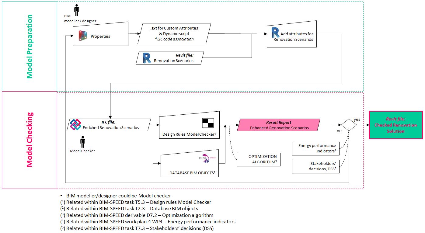
Figure7: Exchange Requirements illustration
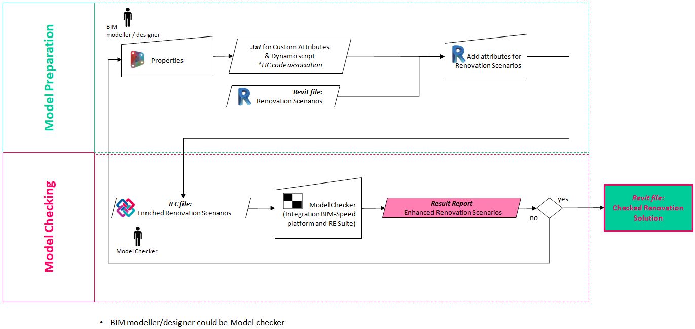
Figure 1: Process Map
The process of rule checking can be broken down to the following four phases: (i) rule interpretation, (ii) building model preparation, (iii) rule execution and (iv) rule check report. The rules used by the BIM-SPEED model checker are defined in JSON files, which are read and parsed by the model checking during checking of the model. These rule files can be edited with a rules editor which parses the JSON files, presents them in a user-friendly way in the interface and allows the user to modify the rules used for checking models. The interface then translates the user input back to JSON to be stored in the rules file.
The addition of custom IFC Attributes and their respective values is required, so that the model can be checked against the design rules. For the demonstration of the workflow under BIM-SPEED, Autodesk Revit has been used as the tool to define custom property sets. Once all custom property sets are defined, a .txt file must be created so that the process of adding the custom IFC Attributes can be potentially automatized and replicated.
After translating the semantic rules to JSON files and preparing the 3D (IFC) model, the objective is to make sure that this IFC model adheres to a set of model requirements, or rules. The model checker therefore is able to read and parse a rule set, read an IFC model, and check if the IFC model meets the requirements defined in the rules set. The methods chosen to handle the association of entities correctly are LIC and PIC. This means that entities within the model that should be considered ‘associated’ are labelled with a LIC code (location identification code). So different entities that are associated contain the same LIC code. This allows the model checker to correctly and efficiently determine what to check and what not.
Once all the rules have been translated to JSON and the model is loaded, the model can be checked. The process for checking a model is as follows:
A tree of entities defined in the model stands to the left. At the top, the model is displayed, and at the bottom a list of errors that have been detected by the model checker is displayed. This list can, as desired, be exported as a .CSV file.
With knowledge of what elements do not adhere to specifications the intent is to suggest actions for the user to take. Specifically, to ensure compliance with the specified rules the element that is not up to spec must be replaced with one that is. RE Suite will attempt to suggest such an alternative element. This, however, requires that a suitable population of potential replacement elements is available.
Within the BIM-SPEED project, STRESS has developed a BIM-element database with available components useable in modelling software. At the time of writing this database contains some 200 elements with enough information to perform comparisons. More importantly, the database is accessible through an API. This enables RE Suite to connect to the database and query for matching elements. Additionally, STRESS is investigating development of a Revit plugin so that the element database can be used directly in the modelling software.
After querying the database RE Suite downloads the result set. Because the API query functionality does not support all relevant criteria RE Suite locally compares based on the unevaluated criteria. The remainder is ordered to minimize cost if such data is available. Finally, the topmost element is suggested as replacement element to the user.
Demonstration Site:
The rules used by the BIM-SPEED model checker are defined in JSON files, which are read and parsed by the model checking during checking of the model. These rule files can be edited with a rules editor which parses the JSON files, presents them in a user-friendly way in the interface and allows the user to modify the rules used for checking models. The interface then translates the user input back to JSON to be stored in the rules file.
The rules used by the BIM-SPEED model checker are defined in JSON files, which are read and parsed by the model checking during checking of the model. These rule files can be edited with a rules editor which parses the JSON files, presents them in a user-friendly way in the interface and allows the user to modify the rules used for checking models. The interface then translates the user input back to JSON to be stored in the rules file.
Regarding the demonstrator model, the addition of custom IFC Attributes and their respective values is required, so that the model can be checked against the design rules. For the demonstration of the workflow under BIMSPEED, Autodesk Revit has been used as the tool to define custom property sets, for the example of the Spanish demonstration building. Once all custom property sets were defined, a .txt file was created (Figure 2) so that the process of adding the custom IFC Attributes can be potentially automatized and replicated for demonstrators in Spain.
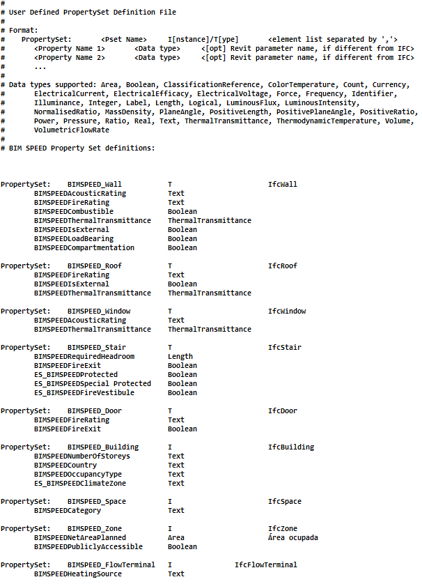
Figure 2: Text file with user-defined properties
After translating the semantic rules to JSON files and preparing the 3D (IFC) model, the objective is to make sure that this IFC model adheres to a set of model requirements, or rules, as defined in the previous chapter. The model checker therefore read and parse a rules set, read an IFC model, and check if the IFC model meets the requirements defined in the rules set. It then presents the results from the model check to the user in a user-friendly manner. Entities within the model that should be considered ‘associated’ are labelled with a LIC code (location identification code). So different entities that are associated contain the same LIC code. This allows the model checker to correctly and efficiently determine what to check and what not. To check whether this method can work for the model checker, the following demonstration was performed (Figure 3). What we see here is a part of an IFC model. An “IFCStairCase” object is selected (red), and all objects that have the same LIC code (or contain the same LIC code) are highlighted in yellow. This allows the model to select entities within the model that should be considered associated with the IFCStairCase entity.
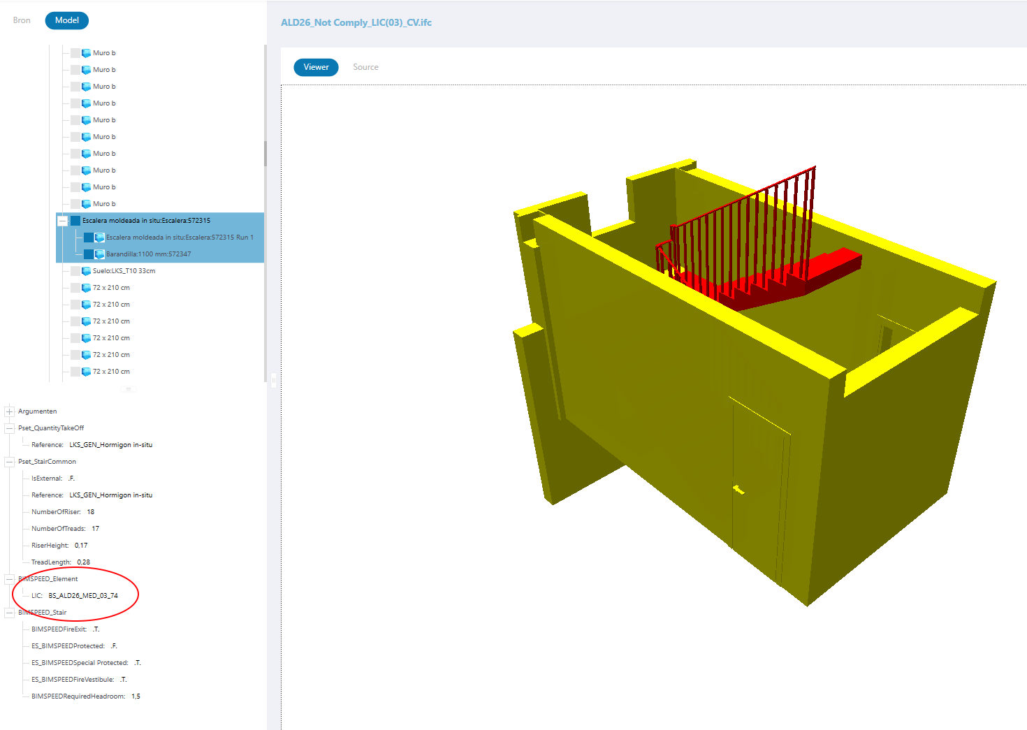
Figure 3: Associating entities using LIC
Once all the rules have been translated to JSON and the model is loaded, the model can be checked. As Figure 4 illustrates, a tree of entities defined in the model stands to the left. At the top, the model is displayed, and at the bottom a list of errors that have been detected by the model checker is displayed. This list can, as desired, be exported as a .CSV file.
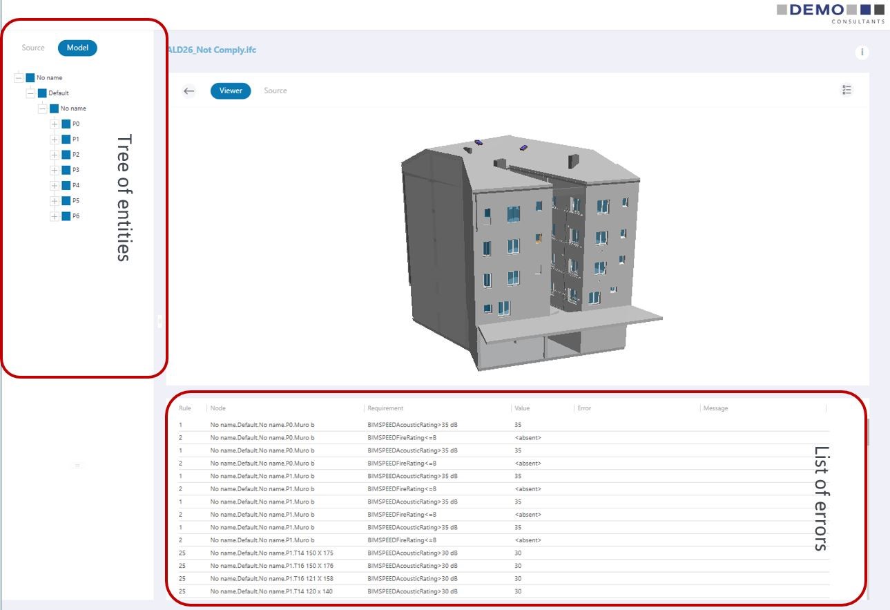
Figure 4: Checked model and it's generated report
The user also can examine these errors in more detail within the model viewer itself as presented below. In Figure 5, the user has selected one of the entries in the list of errors produced by the model checker. The IFC entity that contains the problem (in this case an IFCWindow object) is highlighted in both the model explorer and in the model viewer. The pane at the lower left displays’ properties of the selected entity, which confirms the problem: the requirement specifies that the BIMSPEEDAcousticRating should be larger than 30 dB, but the IFCWindow has a BIMSPEEDAcousticRating equal to 30 dB.
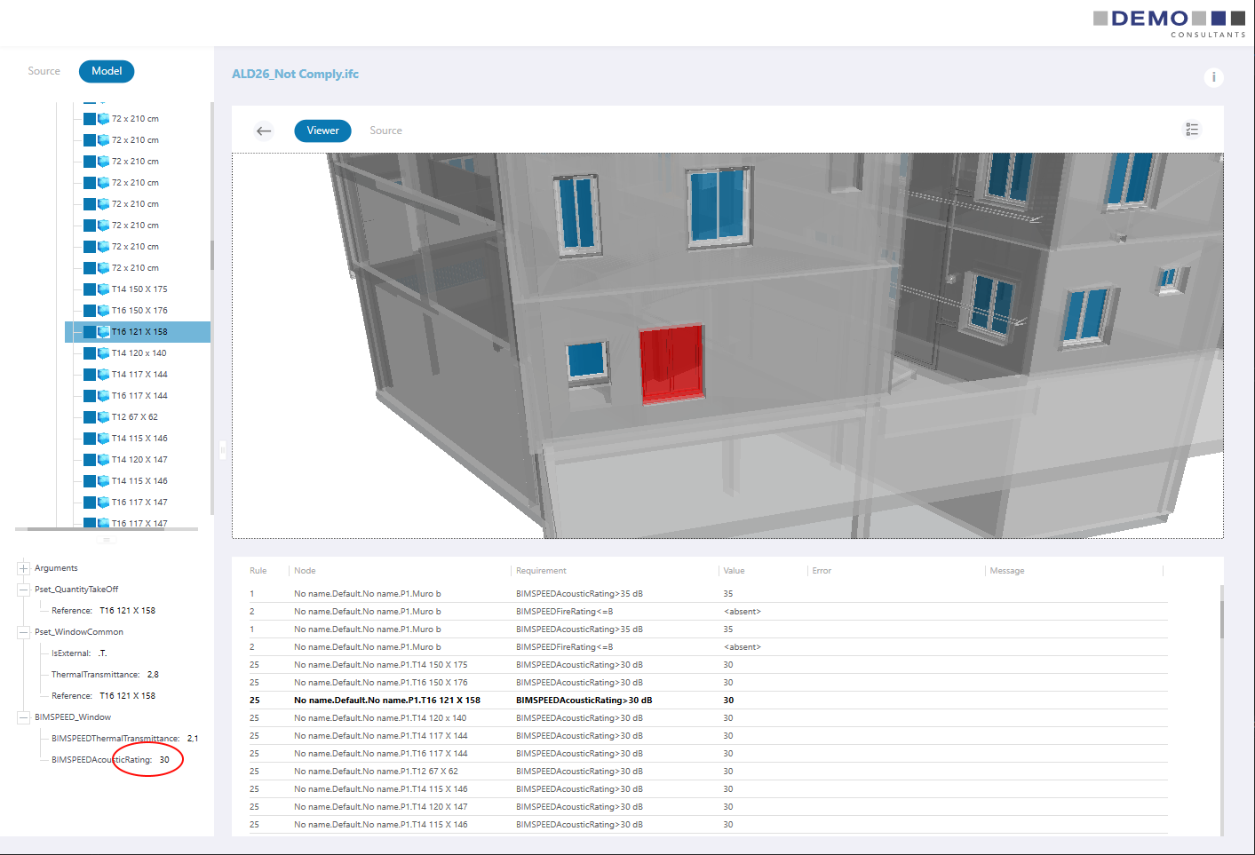
Figure 5: Details of results generated by model checker
With knowledge of what elements do not adhere to specifications the intent is to suggest actions for the user to take. Specifically, to ensure compliance with the specified rules the element that is not up to spec must be replaced with one that is. RE Suite will attempt to suggest such an alternative element. After querying the BIM-element database, RE Suite downloads the result set. Finally, the topmost element is suggested as replacement element to the user. Upon triggering RE Suite from an IFC, the file is downloaded and shown in the RE Suite 3D viewer (Figure 6).
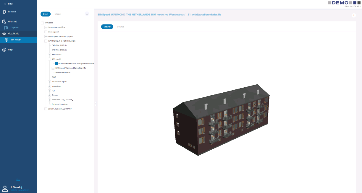
Figure 6: Upon triggering RE Suite from an IFC, the file is downloaded and shown in the RE Suite 3D viewer
The main objectives of this stage to inform the designer about possible errors, as well as guide them to consider a larger range of realistic solutions than is practical without this support. This is particularly relevant in areas where the designer is not an expert or has limited experience. In particular, the model checker tool in which the design rules are implemented, allow the design teams to automatically perform model checks against thermal and acoustic standards, fire safety and accessibility requirements in residential renovation projects located in the countries where BIM-SPEED demo cases are located. In the cases that the model elements fail to comply with the design rules, alternative elements are proposed using objects from the BIM-SPEED database.
Design rules specifications are based on various factors:
The whole process map is included in pre-construction stages. Emphasis on outline conceptual design allows optimizing the whole design stage in order to reduce changes on the renovation scenarios. This tool can also be used for other pre-construction stages such as full conceptual design (stage 5) and coordinated design (stage 6).