- Use cases
- Co-Creation Space
Community
Organizations
Collaboration Partners

- Login
This document aims at describing the ‘BIM-to-BEM process' use case which is implemented as part of BIM-SPEED EU Horizon2020 project, under grant agreement No. 820553 using the “CYPETHERM procedure”. https://www.bim-speed.eu/en. This use case allows to obtain a BEM model of the building starting from a BIM model and exploiting the available data already included in BIM.
The BIM to BEM approach (CYPETHERM procedure) proposed aims at reducing time for the energy model creation compared to current practice, as well as at increasing the accuracy of the models. As most of the building data needed for the energy simulations are already included into BIM models, using BIMs as a data source for the generation of BEMs represents a unique opportunity to increase the effectiveness and the energy efficiency of renovations and move towards the BIM-SPEED goal of 30% time-reduction and 60% energy savings.
The ‘BIM-to-BEM Procedure’ implemented as part of BIM-SPEED project is developed to:
The BEM model can be used to evaluate the following BIMSpeed Energy KPIs:
The “CYPETHERM procedure” provides a practical BIM-to-BEM workflow, to create BEM models starting from BIM models and using a suite of tools developed in the framework of Task 3.2 able to bridge the gap between the BIM models and the BEM models. The UC identifies the steps needed to complete the BIM-to-BEM process, to optimize the interoperability between BIM and BEM and to ensure the completeness and reliability of the energy model. It speeds up the renovation process while reducing the data losses and facilitating the correct flow of information from the geometrical model (i.e. the BIM) to the energy model (i.e. the BEM). The key output of the UC is a BEM model needed to perform the building energy performance analyses.

The main limitation comes from the BIM model used to start the process and the information included that may be not sufficient or not properly set.
Existing guidelines provide instructions to ensure the creation of proper IFC files. Some of the requirements are, as a first example:
Another limitation is that the procedure at the moment do not retrieves HVAC and other thermal zones data from the BIM, but they must be set up directly within the BEM tool.
Data Sheets and Standards:
Connection with BIM modelling applications
The biggest advantage of using IFC technology is the interoperability with all the tools integrated in the Open BIM workflow. The BIMserver.center is free and compatible with all BIM tools capable of generating IFC, including Revit, Archicad, Open BIM Architecture, etc. Once the BIM-BEM bridge is built, it is able to support changes of the BIM model and take them directly to the BEM model, so that the energy calculations are updated accordingly. This one-click synchronization allows the use of these tools as iterative meters supporting the design phase of the project, from the outline to full conceptual design.
In addition, BIMserver.center has an automatic notification system, so that registered users will know when there have been changes in the project. The platform will automatically manage the requirements and incidents detected manually and automatically in the project. This guarantees the consistency of the BIM model and the BEM model and creates a continuous communication bridge with all stakeholders. Each participant in the project will be assigned a role, so that the development of the entire project and the authorship of all modifications will be recorded on the platform.
Connection with BIM SPEED Platform
The BIM-SPEED platform is based on microservices. The communication between the BIM-SPEED platform and the applications (IFC Builder, Open BIM Analytical Model, Open BIM Construction System and CYPETHERM EPlus) is, in fact, a communication between two platforms: the BIM SPEED Platform and the BIMserver.center platform. The workflow is based on cloud (user will be able to access his project at all times through the web) and the link between the two platforms is made by a desktop application capable of containing BIM-SPEED platform and BIMserver.center data simultaneously and able to exchange files between platforms easily.
The name of the tool is BIMSpeed2Bimserver. The procedure to follow to integrate the mentioned tools in the platform is:
This will allow any user of the BIM-SPEED platform to ensure that the files they are uploading are synchronized with the latest version of the information uploaded to BIMserver.center. In addition, this procedure can be iterative, so that the desktop application will serve to update the files as the project progresses.
The procedure to bring information from Kroqi to BIMserver.center will be analogous, creating a two-way data bridge between both platforms. It is important to point out that the user who wants to work in this way will have to have an account in both platforms to have access to the information he wants to synchronize.
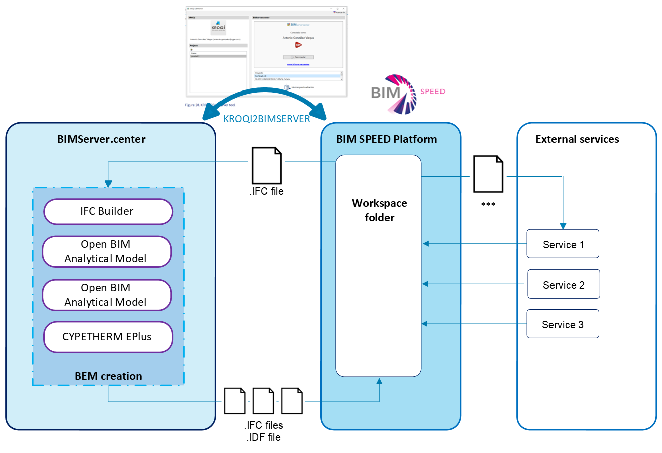
Figure 7: Connection between BIM SPEED Platform and BEMServer.center
All dokuments are licensed as a Creative Commons Attribution-NonCommercial-ShareAlike 4.0 International License
(Attribution-Non-Commercial-ShareAlike 4.0). Further information can be found at
![]()
The documents reflect the current best practice and do not claim to be complete. They should not to be understood in the sense of a generally valid recommendation or guideline from a legal point of view. The documents are intended to support appointing and appointed parties in the application of the BIM method. The documents must be adapted to the specific project requirements in each case. The examples listed do not claim to be complete. Its information is based on findings from practical experience and is accordingly to be understood as best practice and not universally applicable. Since we are in a phase in which definitions are only emerging, the publisher cannot guarantee the correctness of individual contents.
NOT REGISTERED YET?
Register for the Use Case Management Service for free to start creating your first use case.
Registered users can use the download area and the comment functions.

The overall process for BIM-to-BEM workflow using the “CYPETHERM Procedure” is presented in figure below. Essential pre-conditions and input data are:
tools installation (IFC Builder, Open BIM Analytical Model, Open BIM Construction System, CYPETHERM EPlus and the plugin Open BIM - Revit, if needed) and registration to BIMServer.center
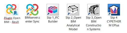
Figure 1: Tools involved in the process
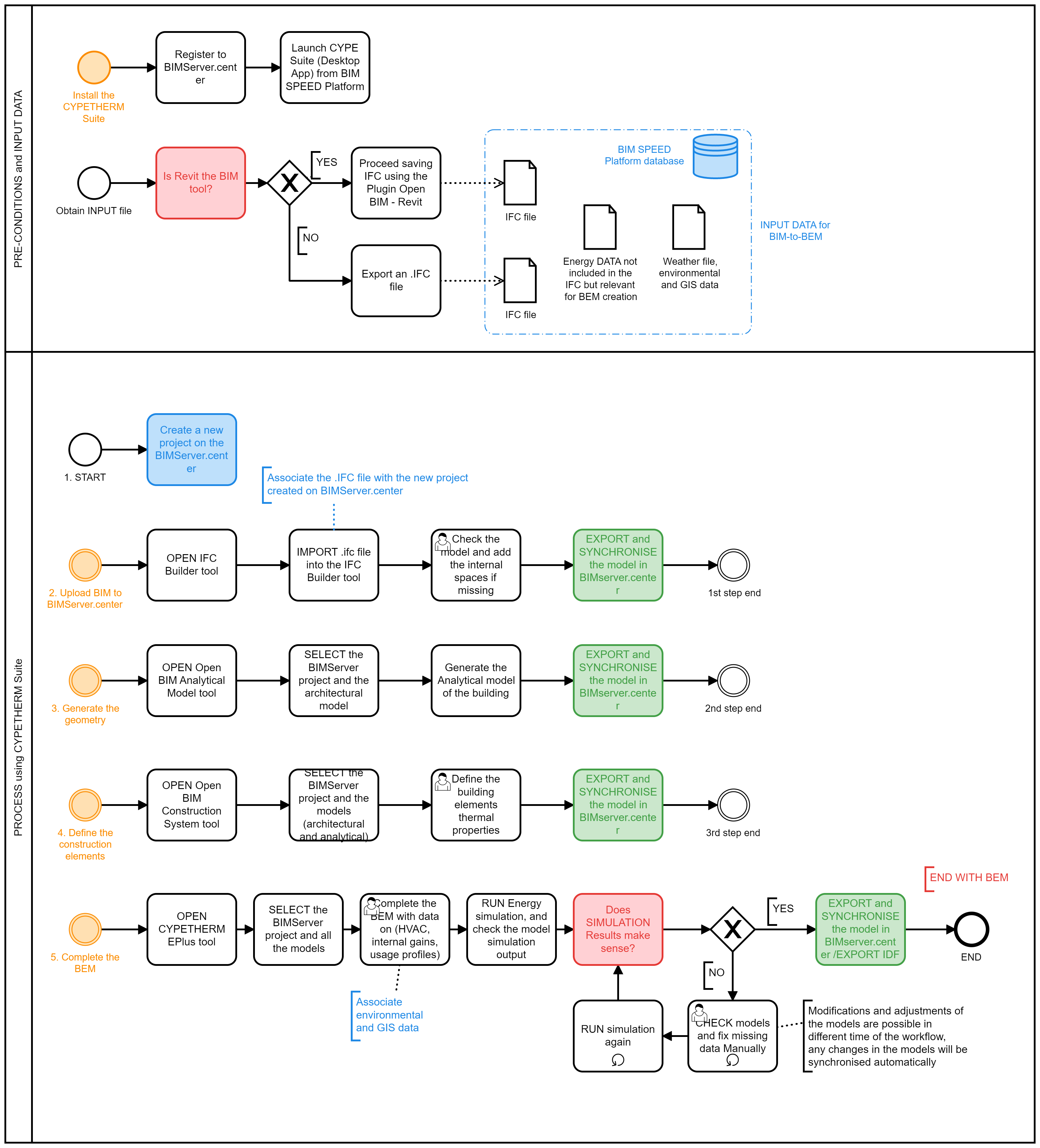
Figure 2: BIM-to-BEM (CYPETHERM Procedure) Process Map
As shown in the image above, the BIM-to-BEM process using the CYPETHERM procedure involves 5 main steps detailed below.
Step 1: Create a New Project on the BIMServer.center
The first step to create a BEM model from a BIM model is to create a new project in BIMserver.center.
Step 2: Upload BIM to BIMServer.centre
When a new project is created, to upload the .ifc file into the Open BIM workflow and associate it to the new project, the IFC Builder tool can be used. It allows also to check the BIM model geometry and, if needed, to make manual adjustments, define the different spaces making up the building and grouped them into different thermal zones.
To carry out the automatic geometric check of the model, the “Results” menu can be used.
After the final check the generated model must be exported (several versions of IFC formats are available) and integrated in the Open BIM workflow simply using the “Export” menu.
Step 3: Generate the geometry
To generate analytical geometric models of buildings the Open BIM Analytical Model must be used. Selecting the specific BIMServer.center project and the architectural model of the building as exported from the IFC Builder tool, the creation of the analytical model will be completed automatically with the Analytical Model Generation button. This process can take a couple of minutes depending on the hardware specifications of the user. Default options are suitable for the majority of the cases.
Once the calculation has finished, the generated analytical model is visible and must be exported back to BIMserver.center using the Export button. The model includes the detailed definition of surfaces, edges and vertexes, as well as their geometric relationship (e.g. which spaces they belong to, adjacencies between surfaces, edges that form a junctions etc).
The Open BIM Analytical Model solves the problem of lack of geometric accuracy and heterogeneity of definition of IFC files generated by different major BIM tools (Revit, ArchiCad, Allplan, etc). From any IFC containing the geometric definition of spaces, this application is able to recalculate its geometry and redefine all the edges and vertices of all the enclosures of the model received as input, so that it is ready to be calculated by subsequent thermal analysis tools.
Step 4: Define the construction elements
Through the use of the Open BIM Construction System tool, once selected the specific BIMServer.center project and both the architectural and the analytical model of the building, the user will be able to create construction systems by layers.
The Open BIM Construction Systems integrates the construction elements that have been defined in the architectural and in the analytical model of the BIM project. It allows users to indicate the following properties of the construction solutions of the project:
The definition of entities can be stored in libraries that can later be imported automatically, so that the definition of construction systems of BIM projects can be more or less automated.
Once the definition of the elements has finished, the model must be exported back to BIMserver.center using the Export button.
Step 5: Complete the BEM
The final completion of the BEM, with the input of all the missing data such as HVAC, operating schedules, set point temperature, internal gains etc. is carried out directly using the CYPETHERM EPlus tool.
The BIMServer.center project and all the models of the building (architectural, analytical, the one with construction elements) must be selected. CYPETHERM EPlus integrates all the elements and the information included in the previous models.
Once the BEM has been completed, a final check of the model must be done running the energy simulation. If the simulation results make sense, it is possible to export the model back to BIMserver.center using the Export button. If the model includes some errors (from the simulation results report) or the results do not make sense, the user must check again the model and fix missing or wrong data manually. Modifications and adjustments of the models are possible in different time of the BEM creation. Any changes in the workflow will be synchronized.
A folder with the .idf file of the BEM is automatically generated on local to be available for other BIMSPEED tools (e.g the Optimization tool and the Calibration tool).
Advantages:
The overall process is further explained through its implementation on the Frigento democase.
Frigento democase is a residential building called “Palazzo Testa Cipriano” located in the historical center of Frigento (Italy) in a densely urbanized context. The building is characterized by a rectangular plant and by a compact volume with a central court. The original building construction year dates back to 1600 with subsequent restoration actions, one of the latest in 1783, date impress on the main entrance. Due to the cultural value of the whole historical center, the building is protected by the Cultural Heritage Office. In 1980 the building was subjected to a consistent consolidation intervention, mostly addressed to the first floor, due to damages caused by an earthquake. The demo case consists of 2 apartments (Flat “Testa” and Flat “Cipriano”) and 2 floors (ground floor and first floor) and it is characterized by stone-brick masonry walls and reinforced concrete and brick mixed floor and roof. In addition to the 2 apartments, on the ground floor, there are also a few unheated rooms. Regarding the HVAC systems, the building is characterized by 2 separated heating systems. Each apartment is equipped by a traditional gas boiler for the heating and the domestic hot water production. No cooling systems or mechanical ventilation systems are installed.
The BIM model of the building have been developed with Revit software and is available in the BIM_SPEED platform. At first, to integrate the Frigento BIM into the Open BIM workflow using the IFC standard, the plug-in Open BIM-Revit has been used to extract information from the BIM model and map data to readable file for CYPETHERM Suite tools.
Step 1 - Create a New Project on the BIMServer.center
As first step, the “BIM SPEED_Frigento_V0” project has been created on the BIMserver.center platform.
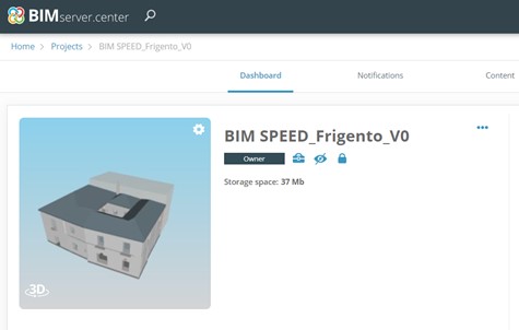
Figure 3: Creation of a new project on the BIMServer.center
Step 2 - Upload BIM to BIMServer.center
Once created the project on BIMServer.center, the .ifc file generated from the plug-in Open BIM – Revit, has been uploaded into the Open BIM workflow and associated to the project with IFC Builder. Using the IFC Builder tool, the Frigento.ifc file has been checked and the internal spaces added.
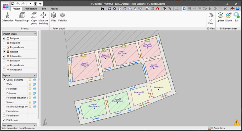
Figure 4: IFC Builder: Frigento model check (geometry and internal spaces)
The model has then been exported back and synchronized in BIMserver.center.
Step 3 – Generate the geometry
The architectural model (generated with IFC Builder) has been open with the Open BIM Analytical model tool selecting also the “BIM SPEED_Frigento_V0” project. The analytical model of the building, with the definition of surfaces, edges, vertexes and their geometric relationship, has been created automatically with the tool. A few simplifications and corrections were automatically made, and 4 different thermal zones were defined and associated to the relevant spaces (defined previously with IFC Builder):
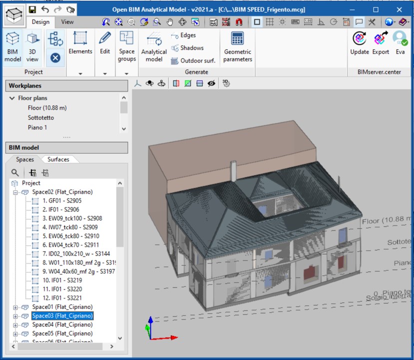
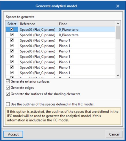
Figure 5: Open BIM Analytical model: creation of the Frigento analytical model
The analytical model, once generated, has been exported once again in BIMserver.center and the project has been synchronized.
Step 4 – Define the construction elements
Using the Open BIM Construction System tool, the “BIM SPEED_Frigento_V0” project has been selected together with the architectural and the analytical models of the building in order to characterize the building elements under the thermal point of view.
The following table summarizes all the materials implemented within the Frigento model to characterize the thermal behavior of the building.
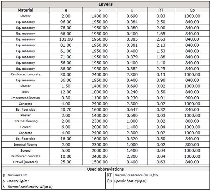
All the building typologies (external walls, party walls, internal partitions, external and internal floors, roofs, etc.) have been defined layer by layer and associated to proper elements.
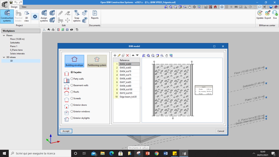
Figure 6: Open BIM Construction system: creation of the stratigraphies
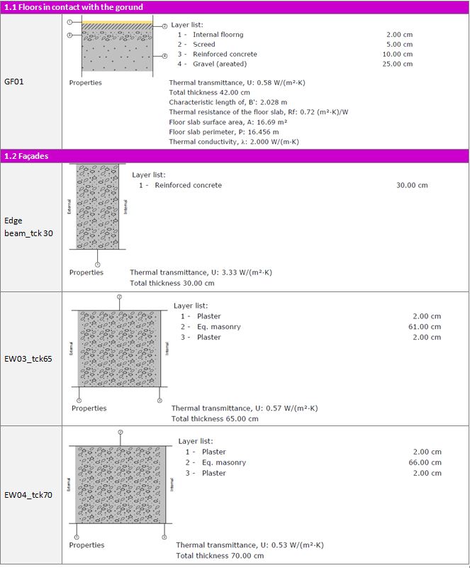
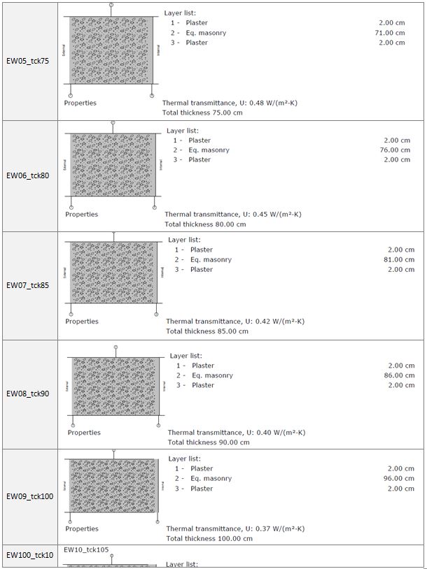
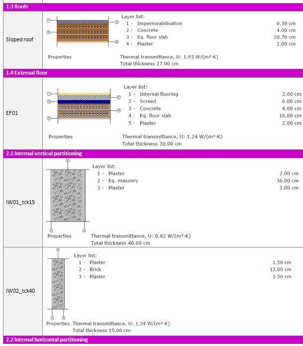
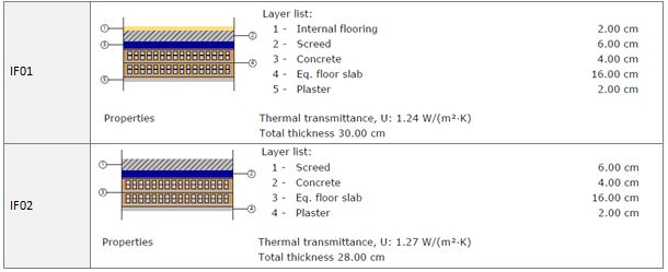
Using the materials as previously defined, all the stratigraphy have been defined and stored within a dedicated library in order to be recalled for future uses. Following table summarizes all the stratigraphy created to characterize the Frigento model.
Table 3: Frigento stratigraphies
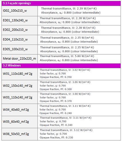
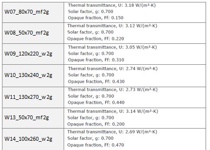
To complete the thermal features of the envelope, also façade openings and windows have been defined as reported in the following table.
Table 4: Frigento openings and windows properties
The enriched .ifc has been exported once again in BIMserver.center and the project has been synchronized ready to move to last step.
Step 5 – Complete the BEM
Once selecting the “BIM SPEED_Frigento_V0” project together with the all the models previously defined and synchronised on the BIMServer.center, the BEM model has been completed with the CYPETHERM Eplus tool.
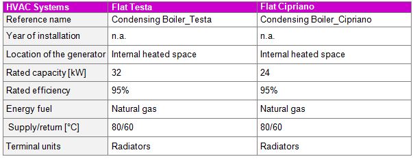
Concerning the weather data, the .epw weather file of the location has been linked to the BEM directly in Cypetherm Eplus, while concerning the HVAC system, 2 separated heating systems (one for each apartment) with condensing boilers used both for the heating and the domestic hot water production have been modelled using the data summarized below.
Table 5: Frigento HVACsystem properties
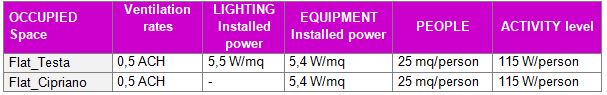
No cooling systems or mechanical ventilation systems are installed while the BEM has been characterized, for each thermal zone, also with reference to the internal gains (equipment, lighting and people), the usage profiles and the systems operating, occupancy, lighting and equipment schedules.
Table 6: Frigento thermal zones properties
Results:
The results of all the previous operations allow to create a complete BEM ready to be calibrated using the new BIM SPEED calibration tool or via traditional and manual validation methods. After the calibration, the BEM can be used to evaluate different energy KPIS and different renovation scenarios assessing energy and costs savings.
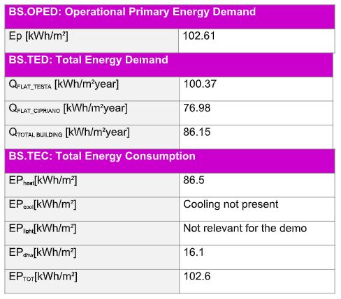
The following Energy KPIs have been calculated using the BEM developed as previously described.
Table 7: Frigento Enery KPIs results
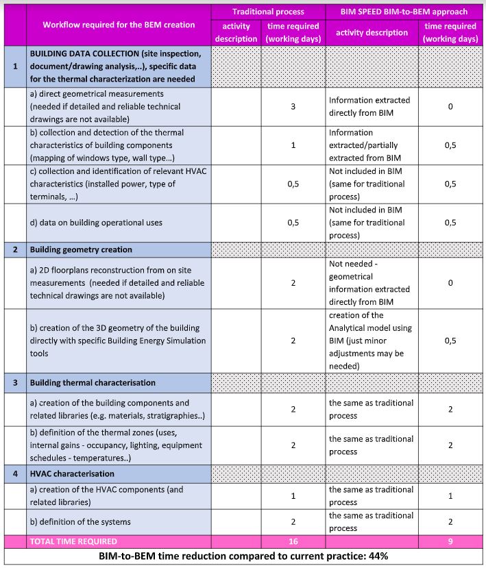
Following table shows the results achieved in terms of time reduction for the BIM-to-BEM process (CYPETHERM procedure) compared to a traditional process. The results show a time reduction of about 44%.
Table 8: Frigento time reduction results
At this stage of a project, the proposed use case, based on the energy simulation results, helps the designer to optimize early decisions and provide a preliminary assessment, in terms of energy savings, of a set of possible renovation solutions (defined according to the conception of need and the outline feasibility phases).
As a pre-requisite to start the implementation of the use case at this stage, the following are:
The IFC file of the building should be characterized by:
At this stage, the proposed use case, support the designer for the completion of the renovation detailed design. The purpose is to provide a comprehensive energy model to be used to fix design elements (e.g. type and thickness of insulation, new heating system features..) and to get all the results needed to support detailed planning approval.
As a pre-requisite to start the implementation of the use case at this stage, the following are: