- Anwendungsfälle
- Co-Creation Space
Community
Organisationen
Kooperationspartner

- Anmelden
openBIM is a method to Building Information Modeling (BIM) that uses open standards such as Industry Foundation Classes (IFC), Building Collaboration Format (BCF), and also services buildingSMART Data Dictionary (bSDD). It has gained popularity in the architecture and construction industries for its ability to facilitate collaboration between various disciplines. openBIM Workflow is also particularly effective in Daylight Design and Analyses, where it can facilitate and help designers, reduce energy use through the implementation of daylight strategies through simulations and communication regarding design decisions.
For example, architects and consultants can perform daylight simulations at the early stages of the design process to determine the ideal placement and size of windows, skylights, and shading devices or glare protection as well as measures to avoid overheating. These simulations can be used to evaluate the impact of design decisions on energy use and occupant comfort, ensuring informed decision-making.
openBIM enables architects and sustainability consultants to collaborate effectively by sharing data and working together in software neutral way, reducing errors and streamlining workflows. Sustainability consultants can access the BIM model, in this case IFC-Models to perform daylight simulations and energy analyses, while architects can incorporate changes based on the results of these analyses, communicated via Issue Management and BCF. This approach ensures that the building design is optimized for energy performance and occupant comfort from the outset.
In summary, openBIM, when combined with daylight design and analyses, can lead to efficient collaboration between architects and daylight experts, lighting designers and sustainability consultants, resulting in significant reductions in building energy use. The use of open standards of buildingSMART such as IFC, BCF, and bSDD facilitates effective collaboration, ensuring that the building design is optimized for both energy performance and occupant comfort.
This Use Case is a Part of a bSI IDM "BIM & BEM" aka Technical Report "BIM and Building Energy Modeling / Performance" and covers only Daylighting.
Lighting Design will remain out of scope.
Daylight varies greatly:
- with geographical region;
- with seasons;
- with the weather condition; and
- with the time of the day
Daylighting Simulations within this Use Case are only based on conditions for CIE overcast Sky for 21st of September at 12:00 p.m.
No theoretical part will be provided.
This Method was used in various past projects like
Related Standards:
ISO 10916:2014 - Calculation of the impact of daylight utilization on the net and final energy demand for lighting
BCF - BIM Collaboration Format
IFC - Industry Foundation Classes
MVD - Model View Defintion
BEM - Building Energy Modeling
IDM - Information Delivery Manual
IDS - Information Delivery Specification
Amidst growing demands to enhance building performance and ensure maximum comfort and functionality for occupants, the lighting designer's primary attention lies in the realm of daylighting and artificial lighting. In the context of larger and intricate projects, their specialized expertise becomes instrumental in identifying and implementing superior design strategies, various formal options, and the most suitable product choices. The ultimate goal is to strike a harmonious balance between energy efficiency, accommodating diverse lighting needs, and ensuring long-term operational sustainability.
Lighting systems encompass both electrical and natural daylighting arrangements, including shading devices or elements. These systems significantly influence heat gain, building thermal efficiency, and overall energy consumption.
Existing Building Case
General Information and Specs: Containerized Office Building for Construction Site
Floor Area: 21m2
Location: Höhr-Grenzhausen
New Building Case
General Information and Specs: Single Family Building, Massive Construction
Floor Area: Available upon request
Location: Gau-Bickelheim
Minimum Requirements to be able to perform Daylight Simulation with DIALux Evo and IFC-Model maybe seen below and also via attached IDS - Information Delivery Specification File (based on IFC2x3 Schema):
Further related Entities from IFC-Schema:
Related bSDD Properties:
https://search.bsdd.buildingsmart.org/uri/buildingsmart/ifc/4.3/class/IfcSpatialZoneLIGHTING
https://search.bsdd.buildingsmart.org/uri/etim/etim/9.0/class/EC003113
https://search.bsdd.buildingsmart.org/uri/nbs/uniclass2015/1/class/PM_35_70_20
https://search.bsdd.buildingsmart.org/uri/nbs/uniclass2015/1/class/PM_40_20_21
https://search.bsdd.buildingsmart.org/uri/nbs/uniclass2015/1/class/Pr_30_59_72_21
IDS - Information Delivery Specification: Will follow soon.
Building Enevelope (Walls, Slabs, Roof, Windows and Doors) and Spaces, Shading Devices:
To import the model successfully, it is essential to be familiar with your software's capabilities and the specific IFC schema it supports. This includes knowing which entities can be read for import, such as ifcSite for the site, ifcWall, ifcWindow, ifcSlab, and ifcRoof, as well as ifcSpaces for the spaces. Consequently, it becomes necessary to identify these entities in your export model. Selecting an appropriate MVD (Model View Definition) is crucial at this stage.
Once the preparation is complete, the subsequent steps can be executed semi-automatically. The ideal scenario is for the import process to run smoothly without requiring any additional enhancements. This allows users to initiate simulations directly, without the need to focus on refining the building model, and instead concentrate on improving the intended results.
Daylight simulation plays a crucial role not just in optimizing energy efficiency but also in enhancing indoor environmental quality and promoting the well-being of occupants. By employing model-based simulations, we can conveniently monitor and predict how a building behaves, ensuring it meets specific standards for daylighting, thus benefiting both energy consumption and the health and comfort of its occupants.
|
EM4 – Initial Architectural Design |
|
|
Project Stage |
Generic: Design (Initial Design Development) bSI: 4. Outline Conceptual Design |
|
Exchange Participants |
Architect, Building Services Engineers, BE Consultant Landscape Architect and Civil Engineer (optional) |
|
Description |
Purpose of Exchange: Establishing architectural baseline for all other disciplines to commence baseline design and systems layouts. The second opportunity to measure potential project performance against baseline requirements. General Information Requirements (GIRs): · Generic depiction of construction systems (e.g., exterior walls, interior walls, floor/ceiling/roof, fenestration locations and extents · Space or Room objects depicting 3D extents of inhabitable spaces with required occupancy and psychrometric (human comfort) values for occupant comfort including lighting levels, temperature, humidity, air quality, etc. · Exterior design elements that may affect building performance (e.g., shading devices, PV locations) · Adjacent context elements which may affect performance (e.g., adjacent buildings, roads, trees, bodies of water and other extensive physical geography) LOX: · Moderate architectural/building element detail – approximate component/system thicknesses, but not detailed component assemblies. Aggregate thermal values and texture/colour depiction of exterior claddings have higher priority; · Moderate fenestration element/system detail – generic indication of unitized glazing system types and extents. Performance values and depiction of adjacent shading devices have higher priority · Low to moderate adjacent context elements. Accurate size/extents of elements that may affect shading and air flow have priority over material and formal detail Special properties or attributes: N/A |
|
Software Functionality |
Export: BIM-authoring tool for architectural design – IFC ‘reference’ export Import: BIM-authoring tool for Structural and Building Services (landscape and civil – optional) design – IFC ‘reference’ import of architectural model BIM viewer for quality assurance / quality checking, validating model has met standard and user-defined exchange requirements – IFC ‘reference’ import of architectural model. Ability to highlight and report errors. Use of standard ‘rulesets’ based on MVD and added user requirements BEM tool for validating concept – IFC import of architectural model, or a specific subset (e.g., spatial model with Space Boundaries, materials/system performance attributes, and psychrometric values) |
|
Related EMs |
EM1, EM2, EM5 |
|
Notes |
1. BIM authoring tool should have ability to capture and assign relevant data (performance, cost, classification) to geometry and pass along to BEM and other analysis tools 2. Some BIM authoring tools may allow for this stage of BEM simulation and analysis to be done internally, but it should be possible to export model data to a separate BEM application for independent simulation and verification of results. 3. May also be a reiterative process, with multiple versions, before settling on a design strategy that meets all performance, functionality, and investment criteria |
|
EM5 – Initial Engineering Design of Building Services Systems |
|
|
Project Stage |
Generic: Design (Initial Design Development) bSI: 4. Outline Conceptual Design |
|
Exchange Participants |
Architect, Engineer, BE Consultant, Owner |
|
Description |
Purpose of Exchange: Establishing initial building services system design and layout baselines based on initial architectural design. The second opportunity to measure potential project performance against baseline requirements. General Information Requirements (GIRs): · Generic depiction of building services systems (e.g., HVAC, Plumbing, Lighting, Power, Communications, etc.). · Generic sizing and location of utility services (e.g., power, water, sewer) including any on-site power generation systems and strategies (e.g., fuel cell, PV, wind, etc.) · Space or Room objects depicting 3D extents of inhabitable spaces with required occupancy and psychrometric (human comfort) values for occupant comfort including lighting levels, temperature, humidity, air quality, etc. · Energy pricing LOX: · Includes ‘single-line’ or axis delineation of piping and ducting, as well as schematics of central HVAC, power, and comm systems. Initial power and thermal load values. · Generic artificial and daylighting schemas Special properties or attributes: N/A |
|
Software Functionality |
Export: BIM-authoring tool for building systems design – IFC ‘reference’ export Import: BIM-authoring tool for architectural design – IFC ‘reference’ import of building services model(s) BIM viewer for quality assurance / quality checking, validating model has met standard and user-defined exchange requirements – IFC ‘reference’ import of building services model(s). Ability to highlight and report errors. Use of standard ‘rulesets’ based on MVD and added user requirements BEM tool for validating concept – IFC import of building services model(s) with architectural model from EM4 |
|
Related EMs |
EM1, EM2, EM4 |
|
Notes |
1. BIM authoring tool should have ability to capture and assign relevant data (performance, cost, classification) to geometry and pass along to BEM and other analysis tools 2. Some BIM authoring tools may allow for this stage of BEM simulation and analysis to be done internally, but it should be possible to export model data to a separate BEM application for independent simulation and verification of results. 3. May also be a reiterative process, with multiple versions, before settling on a design strategy that meets all performance, functionality, and investment criteria 4. Benchmarking requirements can also be included in terms of energy, environmental and economic performance, using key metrics per building type such as the intensity of energy use (EUI) and the energy cost index (ICE), which express the use and cost of energy of the building according to its size, respectively. |
|
EM6 – Design Coordination & Feedback |
|
|
Project Stage |
Generic: Design bSI: 6. Coordinated Design & Procurement |
|
Exchange Participants |
Architect, Engineer, BE Consultant, General Contractor, Product Manufacturer / Supplier, Owner |
|
Description |
Purpose of Exchange: Reiterative process of exchanging domain/discipline models between project design team members to coordinate the geometric and performative aspects of the overall formal design and systems to a high level of detail for costing, procurement, and construction purposes. General Information Requirements: · Specific depiction of construction systems (e.g., exterior walls, interior walls, floor/ceiling/roof, fenestration locations and extents · Space or Room objects depicting 3D extents of inhabitable spaces with required occupancy and psychrometric (human comfort) values for occupant comfort including lighting levels, temperature, humidity, air quality, etc. · Exterior design elements that may affect building performance (e.g., shading devices, PV locations) · Site model and adjacent context elements which may affect performance (e.g., adjacent buildings, roads, trees, bodies of water and other extensive physical geography) · Specific depiction of building services systems (e.g., HVAC, Plumbing, Lighting, Power, Communications, etc.). · Specific sizing and location of utility services (e.g., power, water, sewer) including any on-site power generation systems and strategies (e.g., fuel cell, PV, wind, etc.)
LOX: · High architectural/building element detail – exact component/system thicknesses and detailed component assemblies. High fenestration element/system detail – exact indication of unitized glazing system types and extents. Thermal values and material depiction of each component; · Low to moderate site and adjacent context elements. Accurate size/extents of elements that may affect shading and air flow have priority over material and formal detail · Specific geometric delineation (cross section sizes, lengths, fitting locations) of piping, ducting, and conduits, as well as mechanical, power, and comm equipment. Specific power, performance, and thermal load values. · Specific artificial and daylighting schemas Special properties or attributes: N/A |
|
Software Functionality |
Export: BIM-authoring tool for architectural and building systems design – IFC ‘reference’ export Import: BIM-authoring tool for architectural and building systems design – IFC ‘reference’ import all models BIM viewer for quality assurance / quality checking, validating model has met standard and user-defined exchange requirements – IFC ‘reference’ import of all model(s). Ability to highlight and report errors. Use of standard ‘rulesets’ based on MVD and added user requirements BEM tool for validating concept – IFC import of all model(s) |
|
Related EMs |
EM4, EM5 |
|
Notes |
1. BIM authoring tool should have ability to capture and assign relevant data (performance, cost, classification) to geometry and pass along to BEM and other analysis tools 2. Some BIM authoring tools may allow for this stage of BEM simulation and analysis to be done internally, but it should be possible to export model data to a separate BEM application for independent simulation and verification of results. 3. May also be a reiterative process, with multiple versions, before settling on a design strategy that meets all performance, functionality, and investment criteria |
|
EM9 – Requirements for Sensors & Controls |
|
|
Project Stage |
Generic: Pre-Construction (Procurement) bSI: 6. Coordinated Design & Procurement, 07. Production Information |
|
Exchange Participants |
Engineer, BE Consultant, GC, Product Manufacturer / Supplier, Commissioning Agent |
|
Description |
Purpose of Exchange: Collection of power and communication requirements for sensors and controls of HVAC, lighting, and any other automated systems which have an influence on thermal performance and occupant comfort General Information Requirements: · System and Device identification · IoT Data Protocols · IoT Network Protocols · IoT Security Protocols/Requirements/Standards (e.g., NIST 800 Series https://www.nist.gov/itl/publications-0/nist-special-publication-800-series-general-information) LOX: · May be equal to EM7 with additional GIRs Special properties or attributes: N/A |
|
Software Functionality |
Export: … Import: … |
|
Related EMs |
EM6, EM7, EM8 COBie |
|
Notes |
1. Consider information from field level (e.g., device specification, geolocation), control level (e.g.,, logical connection, schedules, setpoints) and supervisory level (e.g.,, alarms, events, historical data access). 2. This EM may also consider the different Building Automation System (BAS) communication protocols, data representations and interfaces (in terms of requirements and software functionalities) |
|
EM12 – Documentation of Existing Conditions for Recommissioning |
|
|
Project Stage |
Generic: Pre-Design, Recommissioning / Decommissioning bSI: 9. Operations & Maintenance, 10. Disposal |
|
Exchange Participants |
Architect, Engineer, BE Consultant, Owner |
|
Description |
Purpose of Exchange: Collection of geometry and data from existing conditions in making informed decisions related to energy performance in a project recommissioning (also known as retrofit or refurbishment). General Information Requirements: · Climate data · Energy costs · Adjacent context elements which may affect performance (e.g., adjacent buildings, other extensive physical geography) · Spaces and Thermal Zones · Occupancy · Last 3-5 years bills related to energy consumption · Exterior envelope and thermal characteristics of opaque and transparent assemblies · Presence and analysis of thermal bridges · Restoration works done during the lifetime of the building · Structural characteristics of foundations, walls, slabs, etc. · Unoccupied spaces such as attics, cellars, etc. · Existing Building Services systems (aka MEP – Mechanical-Electrical-Plumbing) · Renewable energy systems · Vertical transport systems (lifts, escalator, etc.) · Artificial lighting and daylighting systems · Mandatory building codes and standards · Mandatory energy efficiency standards and/or performance improvement incentives · Former certifications such as: · Building permit authorization / occupancy permit · Historical preservation / protection · Energy / sustainability performance certificate (e.g., LEED, BREAM, etc.) · Structural suitability · … LOX: The level of information of an existing building could be very accurate via LIDAR survey, but during a preliminary energy analysis it is useless to have such a detailed geometric model as it considers only the volumes enclosed by walls, ceiling, windows, etc. Most BIM and BEM applications require the translation to rationalized 3D models with regularized surfaces and semantic definitions. Special properties or attributes: N/A
|
|
Software Functionality |
Export: Point cloud data from LIDAR scanning (point cloud) of existing conditions Import: Point clouds |
|
Related EMs |
EM1, EM2, EM3 COBie |
|
Notes |
1. Historical buildings are usually very different from each other as much as modern structures. Typical software parametric features are not usable for modelling and energy analysis, as the physical and thermal characteristics are very different from modern structures. For this reason, a new database for the definition of these characteristic is recommended. The structure of this data base should be based on the same standards used for bSDD. 2. Some ESCos may require, during the preliminary analysis, interviews with occupants for the correct sizing of HVAC to meet the needs of the occupants. 3. When dealing with an existing building, especially if the building is historical, the drawings deposited in the different authorization offices seldom coincide with the existing conditions. When the documentation is insufficient or not reliable, it is necessary a survey with the use of laser scanning (LIDAR) and/or photogrammetry to acquire reliable geometric data. This can then be integrated with any energy performance parameters necessary for energy simulation. 4. Existing building services systems may need to be identified by manual survey and entered into a BIM system to find any possible improvement and/or constraints to use more efficient technologies. 5. Any normative and cultural protection constraints must be documented to avoid disallowed interventions |
All dokuments are licensed as a Creative Commons Attribution-NonCommercial-ShareAlike 4.0 International License
(Attribution-Non-Commercial-ShareAlike 4.0). Further information can be found at
![]()
The documents reflect the current best practice and do not claim to be complete. They should not to be understood in the sense of a generally valid recommendation or guideline from a legal point of view. The documents are intended to support appointing and appointed parties in the application of the BIM method. The documents must be adapted to the specific project requirements in each case. The examples listed do not claim to be complete. Its information is based on findings from practical experience and is accordingly to be understood as best practice and not universally applicable. Since we are in a phase in which definitions are only emerging, the publisher cannot guarantee the correctness of individual contents.
NOCH NICHT REGISTRIERT?
Registrieren Sie sich für den Use Case Management Service kostenlos, um Ihren ersten Use Case zu erstellen.
Registrierte Benutzer können den Download-Bereich und die Kommentarfunktionen nutzen.

Process Map
https://cawemo.com/share/38e02e30-32f4-49d4-b55f-a0cd19825b68
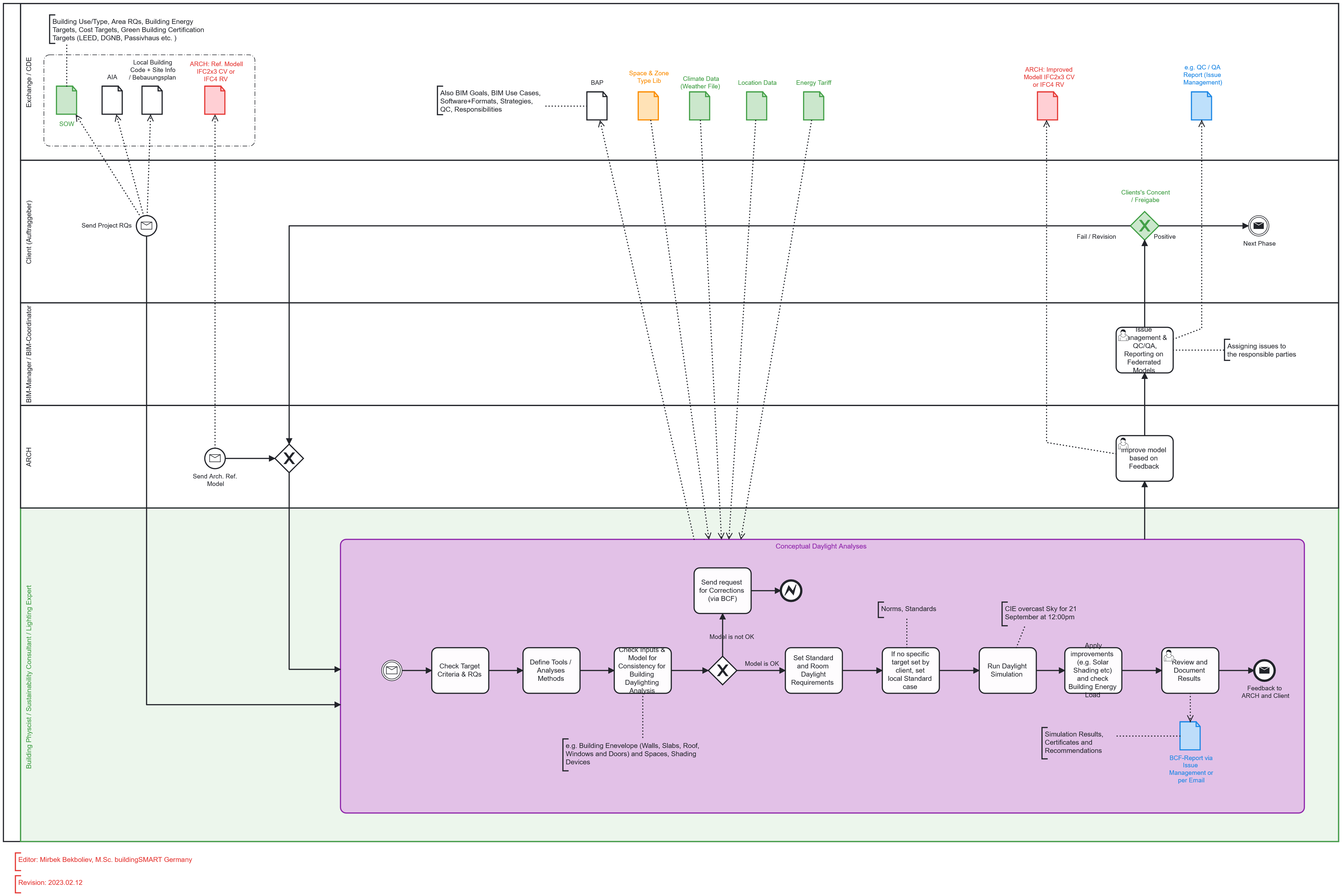
The process described is the workflow for conducting a daylight analysis during the building design phase. It involves various stakeholders like the employer/client, architect, sustainability consultant/lighting designer/energy auditor, and the BIM manager/coordinator. Here's a step-by-step breakdown of the process:
Scope of Work Definition: The scope of work is defined based on various factors, including the building use/type, area requirements, building energy targets, cost targets, and green building certification targets like LEED, DGNB, Passivhaus, etc.
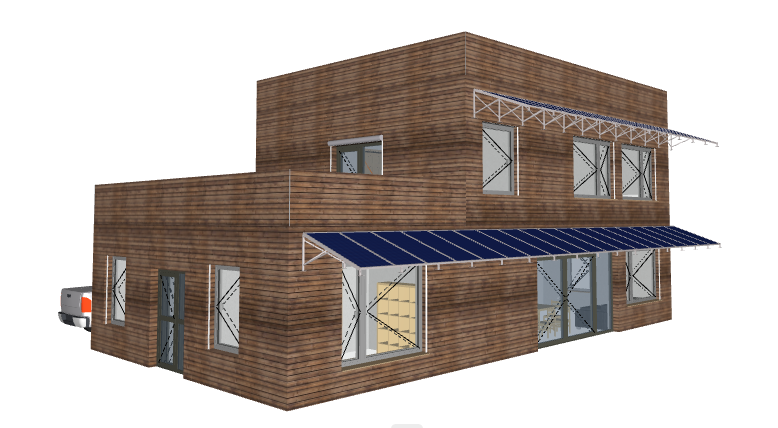
Case 1 New Building - Single Family Home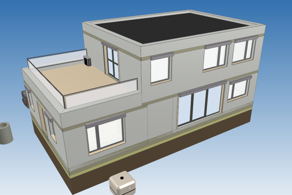
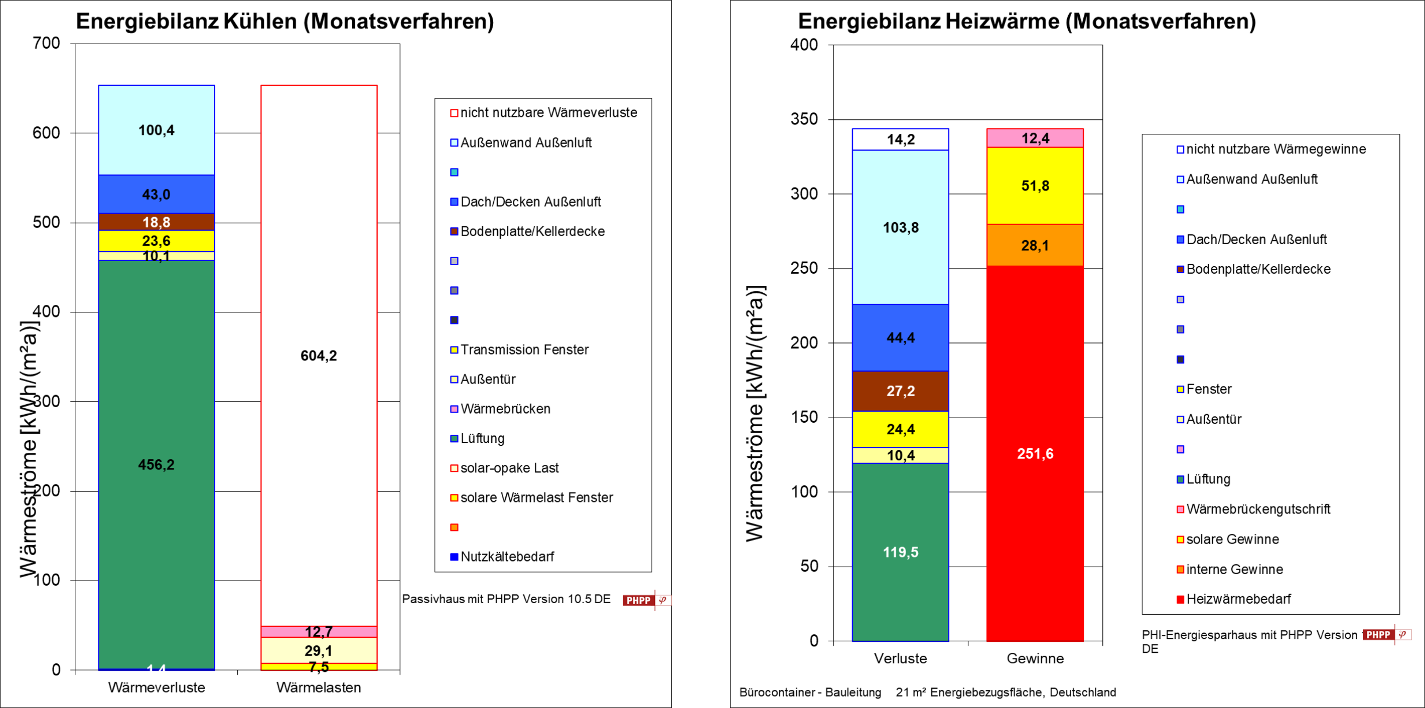
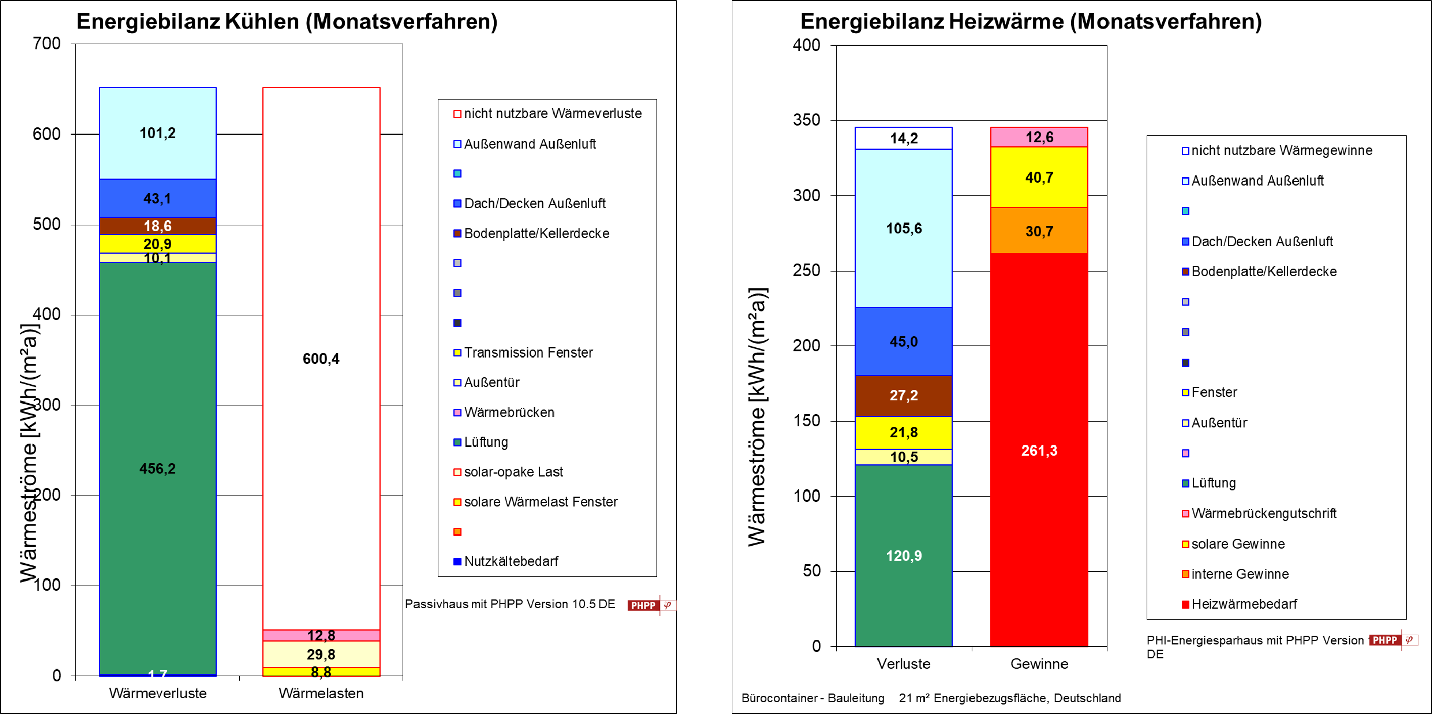
Case 2 Existing Building - Office Building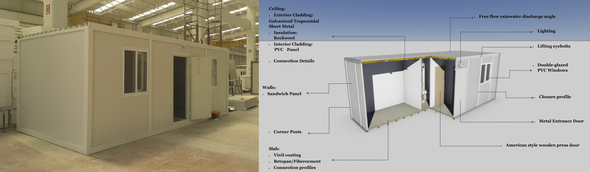
Employer Information Requirements (EIR): The EIR is prepared for BIM, which includes all the project requirements, roles, disciplines, and exchange formats like IFC (Industry Foundation Classes) and BCF (BIM Collaboration Format) for information exchange.
Request for Proposal (RFP): The client sends the information package, including the scope of work and EIR, as an RFP to potential contractors. Contractors submit their proposals based on the provided information.
Daylight Analysis Start: Once all parties agree on the project, the daylight analysis phase begins. An Architect sends a reference IFC-Model for export purposes, which serves as a starting point for the analysis.
See above mentioned building models from Case 1 & 2.
Checking Target Criteria & Requirements: The designer reviews the target criteria, client's requirements, and relevant building codes to understand the objectives of the daylight analysis.
Defining Tools and Analysis Methods: Suitable software tools and analysis methods are selected to perform the daylight analysis effectively.
Checking Inputs & Model Consistency: The designer ensures that the building model (including the building envelope, spaces, shading devices) is consistent and suitable for daylight analysis. Any issues identified are communicated to the architect through BCF.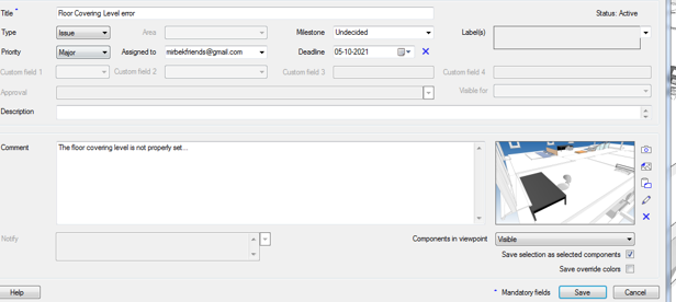
Climate and Location Data: Climate data, such as weather files, is obtained for simulation purposes. This data is essential for evaluating daylight conditions at the project's location.
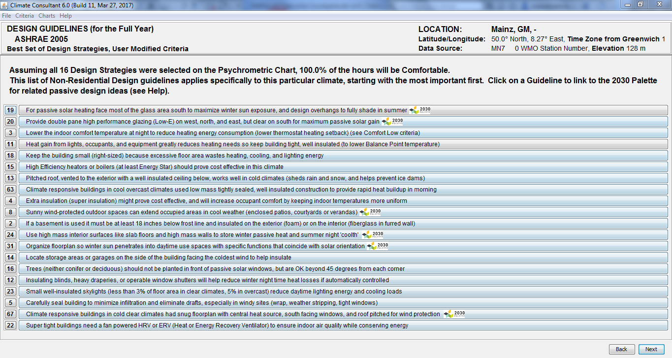
One could also use Tools for Bioclimatic Analyses
See Example Psychrometric Chart for Startegies that could be applied to Mainz Area based on Weather Data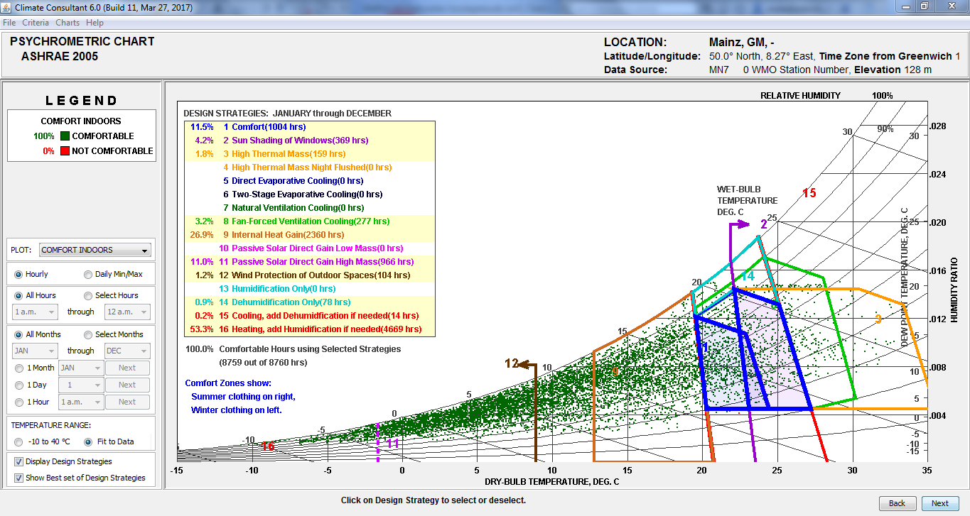
Setting Daylight Requirements: If specific daylight targets are not set by the client, local standard cases will be applied as the baseline for analysis.
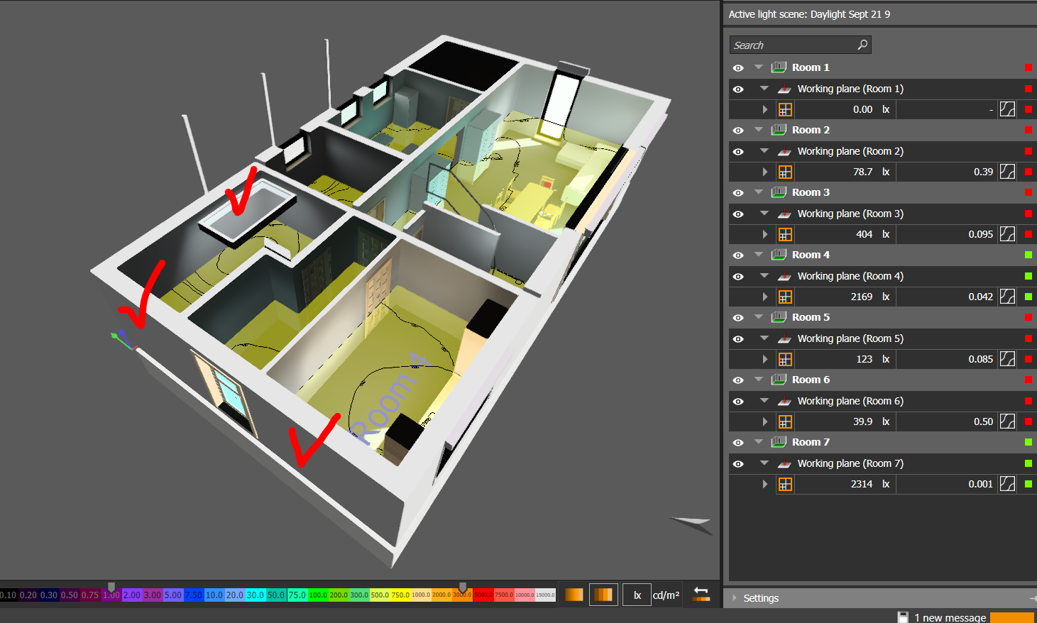
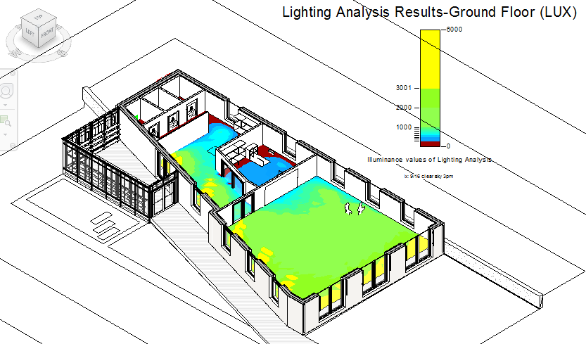
Daylight Simulation: The daylight simulation is performed based on specific conditions (e.g., CIE overcast sky for 21st September at 12:00 pm). Software tools may allow applying design measures like solar shading to improve daylighting.
Case 1 New Builidng - Current State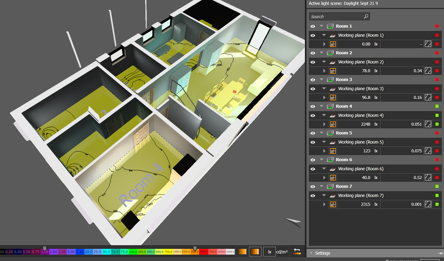
Case 2 Existing Building - Current State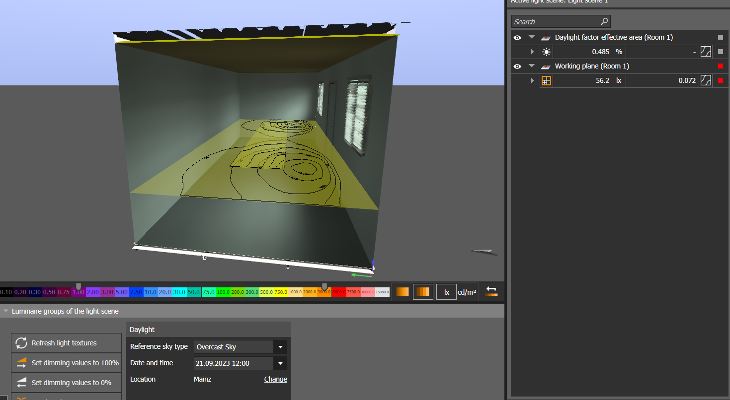
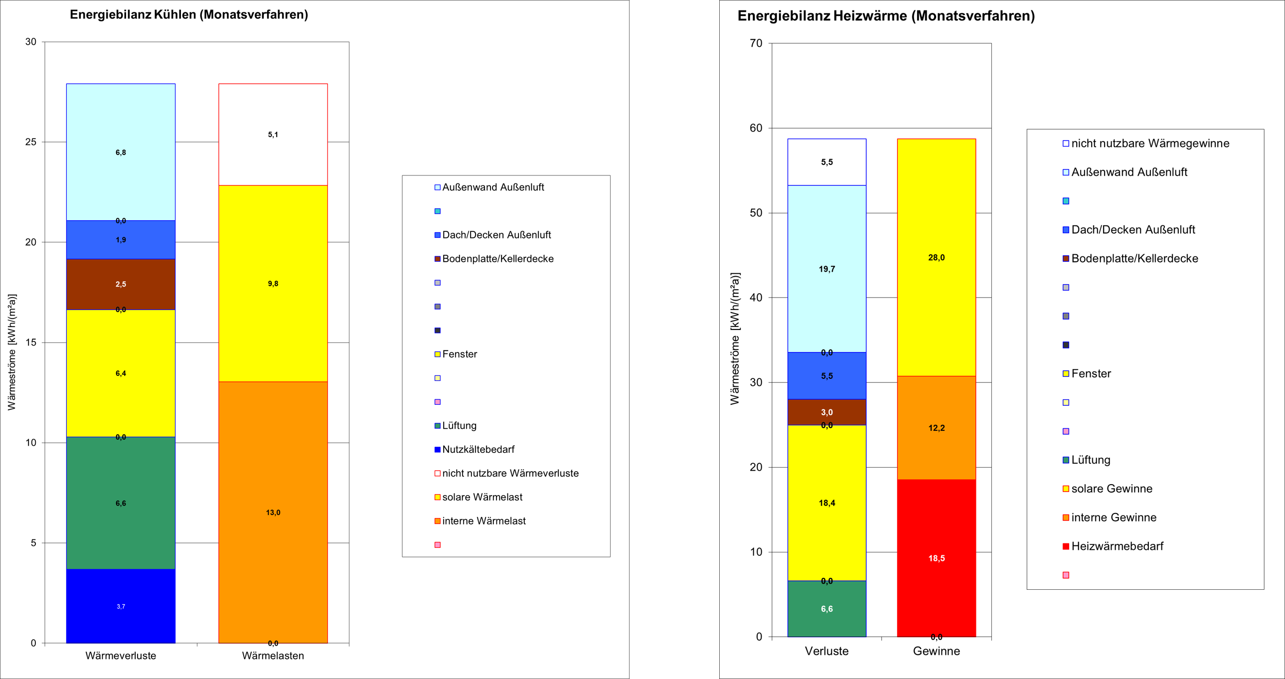
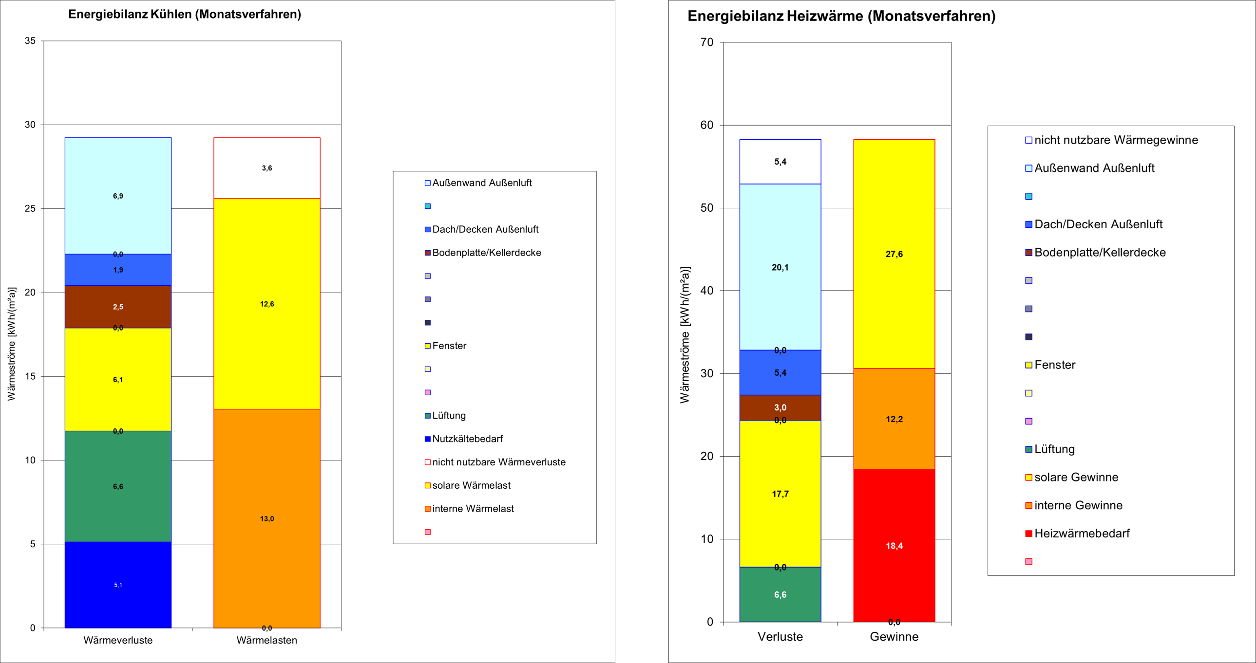
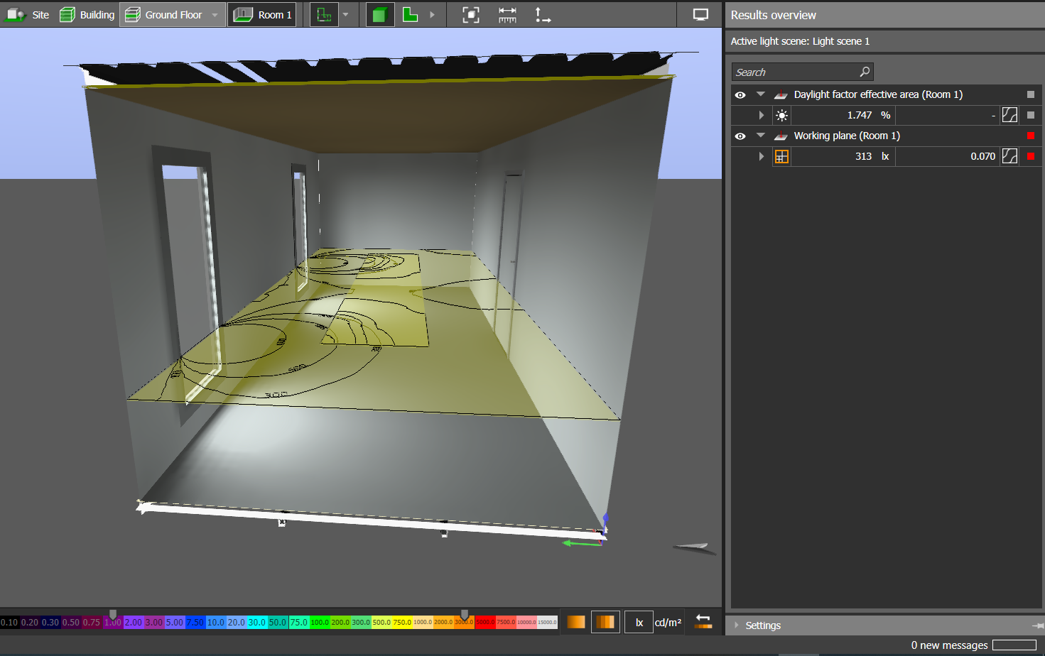
Review and Documentation of Results: The results of the daylight simulation are reviewed and documented. This includes certificates and recommendations for the architect and the client.
Furthermore, utilizing BCF-based communication offers a valuable chance to enhance collaboration and comprehension among stakeholders, while also shedding light on particular concerns within the model. In this instance, the feedback, simulation results, and narratives were all conveyed through the BCF and the issue management platform in unison.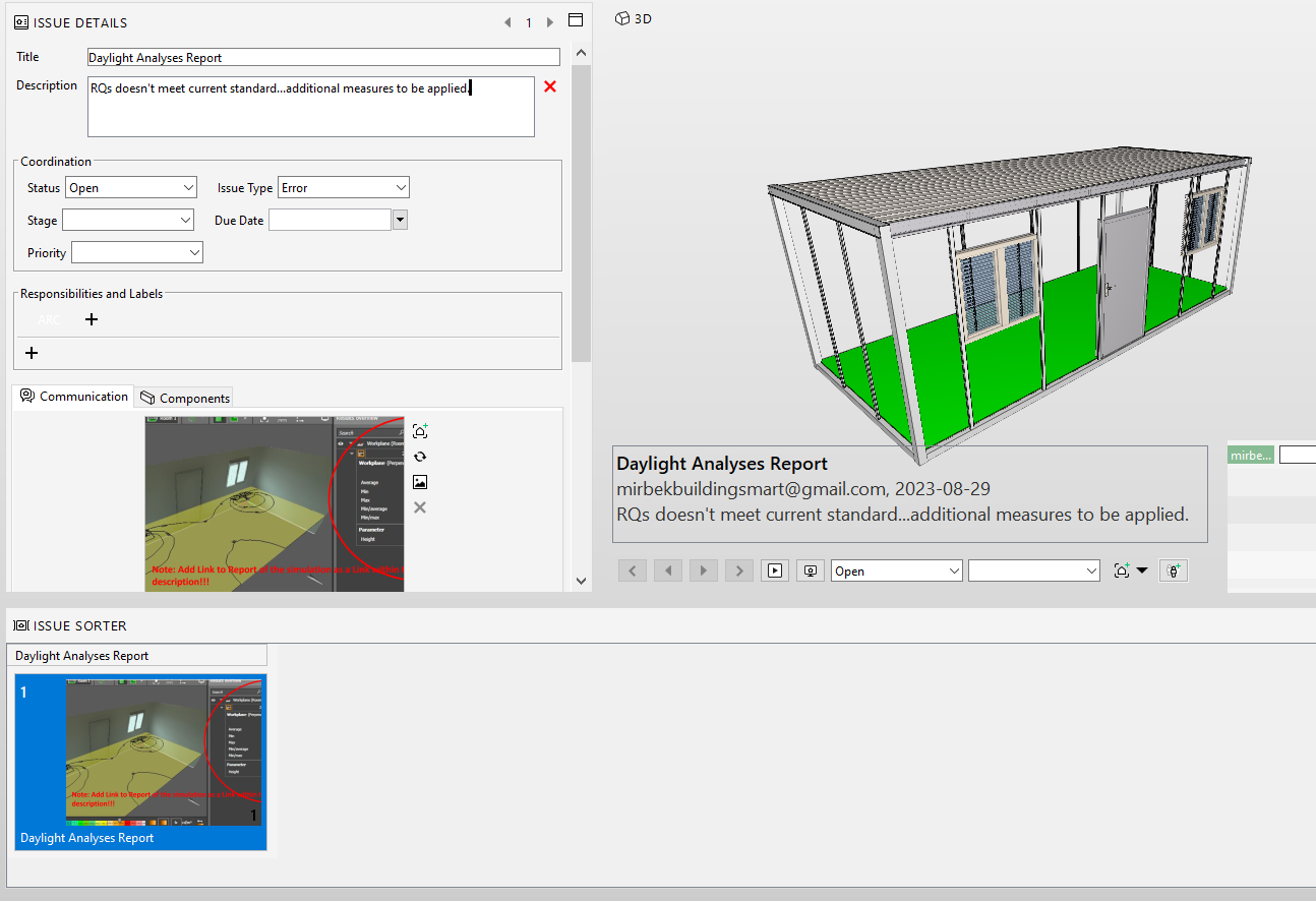
Feedback and Improvement: Based on the feedback and recommendations, the architect improves the IFC-Model to incorporate the necessary design changes.
Issue Management & QC/QA: The BIM manager or coordinator, depending on the company's size, performs issue management and quality control/quality assurance checks on the federated models to ensure accuracy and consistency.
Reporting and Approval: Once the design meets the client's requirements and relevant daylight standards and norms, the project proceeds to the next phase.
The described process is essential to ensure that the building design incorporates proper daylighting strategies, meeting both client expectations and sustainability goals.