- Anwendungsfälle
- Co-Creation Space
Community
Organisationen
Kooperationspartner

- Anmelden
NOCH NICHT REGISTRIERT?
Registrieren Sie sich für den Use Case Management Service kostenlos, um Ihren ersten Use Case zu erstellen.
Registrierte Benutzer können den Download-Bereich und die Kommentarfunktionen nutzen.

All documents are licensed as a Creative Commons Attribution-NonCommercial-ShareAlike 4.0 International License
(Attribution-Non-Commercial-ShareAlike 4.0). Further information can be found at
![]()
The documents reflect the current best practice and do not claim to be complete. They should not to be understood in the sense of a generally valid recommendation or guideline from a legal point of view. The documents are intended to support appointing and appointed parties in the application of the BIM method. The documents must be adapted to the specific project requirements in each case. The examples listed do not claim to be complete. Its information is based on findings from practical experience and is accordingly to be understood as best practice and not universally applicable. Since we are in a phase in which definitions are only emerging, the publisher cannot guarantee the correctness of individual contents.
This document aims at describing the use case ‘Geometrical verification of As-Built BIM Models’, which is implemented as part of the BIM-SPEED EU Horizon 2020 project.
The aim of the BIM-SPEED project is to:
The general objectives of deviation analysis is to ensure the following:

One of the main objectives of the BIM-SPEED project is to reduce the time of deep renovation projects by 30%. Deviation analysis carried out for geometrical verification of 3D model based on laser scans of existing building allows time reduction and enhances reliability of the as-built 3D BIM model by:
With regard to geometry, the existing planning documents and the point clouds to be created from the building are of particular importance for creating and checking the model for geometrical correctness. Beside that it is necessary to consider the geo-coordinates and the buildings alignment while creating a 3D model of the as-build state, it is the only way that model of different disciplines can be consolidated.
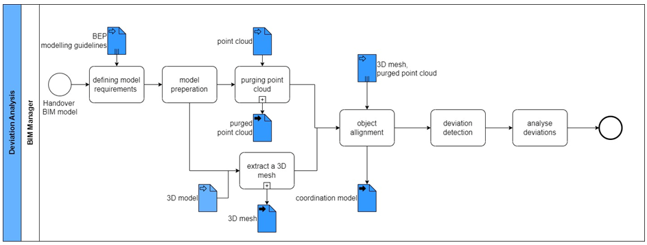
Figure 7: Data exchange between activities within Deviation Analysis
Exchange requirements identified for this use-case are indicated as input and output for every activity performed in the execution of the use case:
Within the framework of model creation it has to be ensured whether the existing as-built documents correspond to the actual condition of the as-built buildings or whether there are deviations. 3D models for renovation projects are often generated on the basis of 2D drawings and therefore represent the status quo in the drawings, depending on the objective of the project and planned activities a 3D model corresponding with the exact as-built situation is required. The most accurate way to get the 3D model matching with the as-built situation is by the use of a laser scan point cloud. Doing laser scans of the inner and outer surfaces of the building leads to an exact representation of the building in form of a point cloud. The point cloud is to be further processed and afterwards used to compare it with the already existing 3D model; results are measurable deviations, which provides information on whether the model needs adjustments or not.
The following process map gives an overview of the specific process step “deviation analysis”.
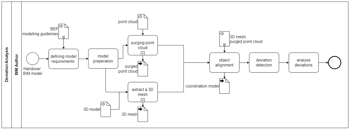
Figure 1: Process map Deviation Analysis
The 3D BIM model of the existing building is prepared based on model requirements, with the possibility of generating the model from existing 2D drawings. The point cloud derived from laser scans are imported and purged, thereby removing all unnecessary points. Several point clouds are aligned by rotating and adjusting the height in order to compile the combined scans to one point cloud (called “manually registration”). Simultaneously, a 3D mesh is extracted from the existing 3D model and the mesh and point cloud are analyzed for deviations. This manual alignment of both will be used to determine the deviation of the 3D BIM model from the as-built situation. This allows to decide if the 3D BIM model can be used for further use cases.
Demonstration site:
Deviation analysis of the existing 3D model against the available point cloud has been carried out on the Dutch Demo site located in Warmond. The 3D model was generated based on 2D drawings, while in parallel, a laser scan of the surrounding and outer shell of the building had been done.
The first step carried out was to create a 3D mesh of the 3D model generated from 2D drawings.
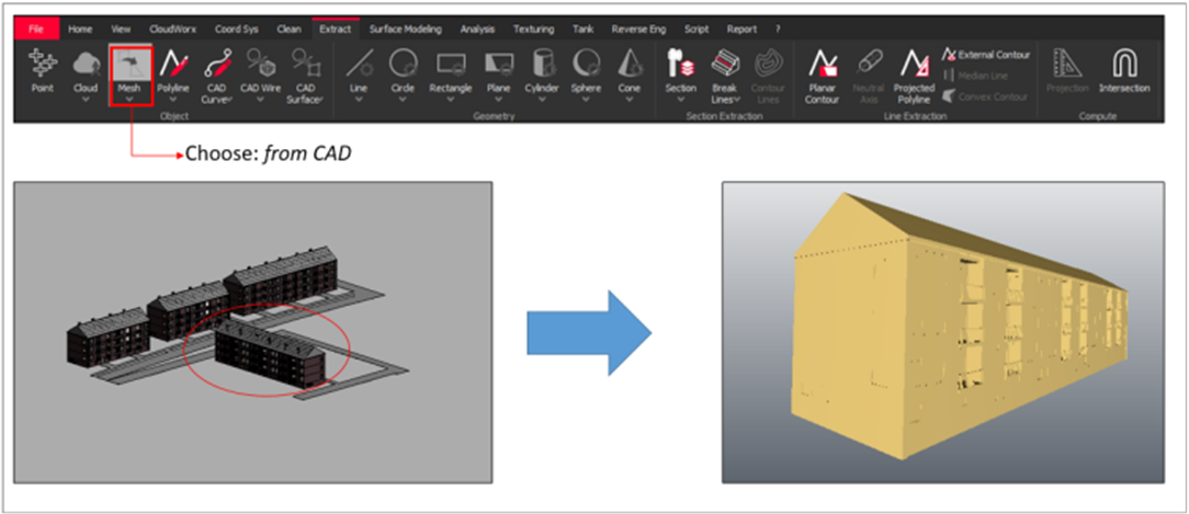
Figure 2: Creation of 3D mesh
The laser scans on site contain all collected information as individual point clouds. In order to create a single point cloud, the several scans have been combined, by the following steps:
Import : The laser scans are imported to Leica Cyclone, thereby the point clouds are compiled as unregistered.
Purge scans: The unregistered point clouds are checked upon which the mirrored and unnecessary points (for instance, wrong measurements due to mirroring effects of windows or flat surfaces like puddles) from point clouds are removed, thereby purging the point clouds.
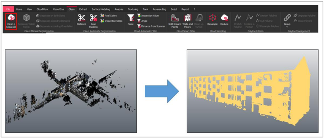
Figure 3: Purging of point cloud
Alignment: The two separate purged scans are chosen, rotated and aligned in order to optimize adjustment. The result obtained is a registered and aligned scanned model.
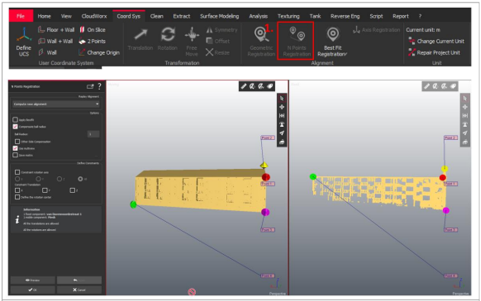
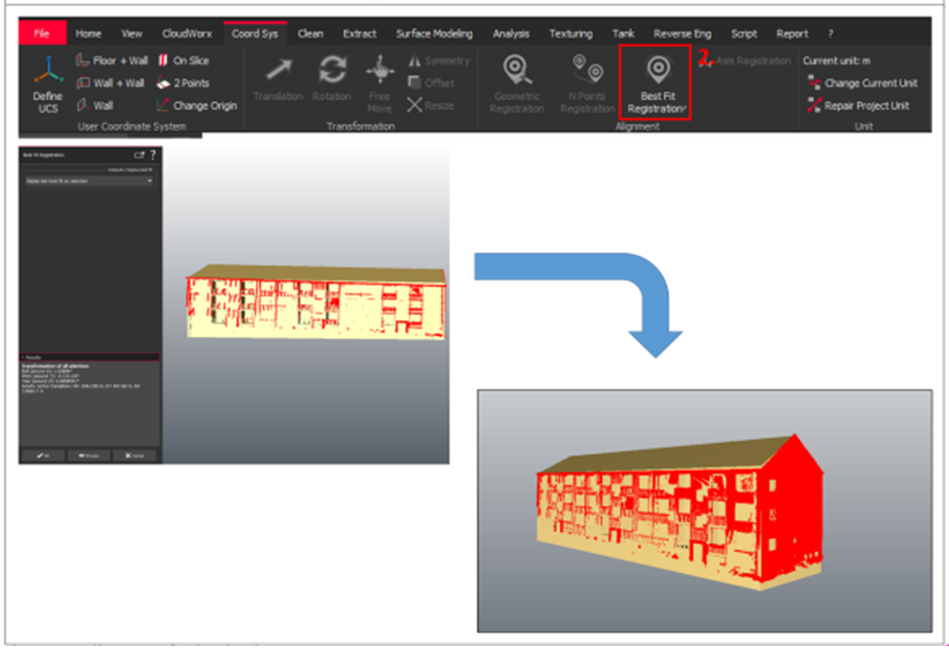
Figure 4: Aligning of point cloud
Evaluation of deviation analysis: Upon manual alignment, the results are optimized by the computer to reach the best possible results, which are then reviewed in order to check if the alignment is accurate enough. The errors and their weights are checked and the end result of this stage is a combined scan of the point cloud registration.
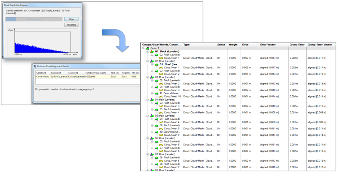
Figure 5: Analyzing and optimizing results
The results from deviation analysis performed on the Dutch demonstration site yielded the results shown in the image below. The blue color indicates that the point cloud differs with the inner direction of the building shell, while red indicates deviation in the point cloud to the outer surrounding.
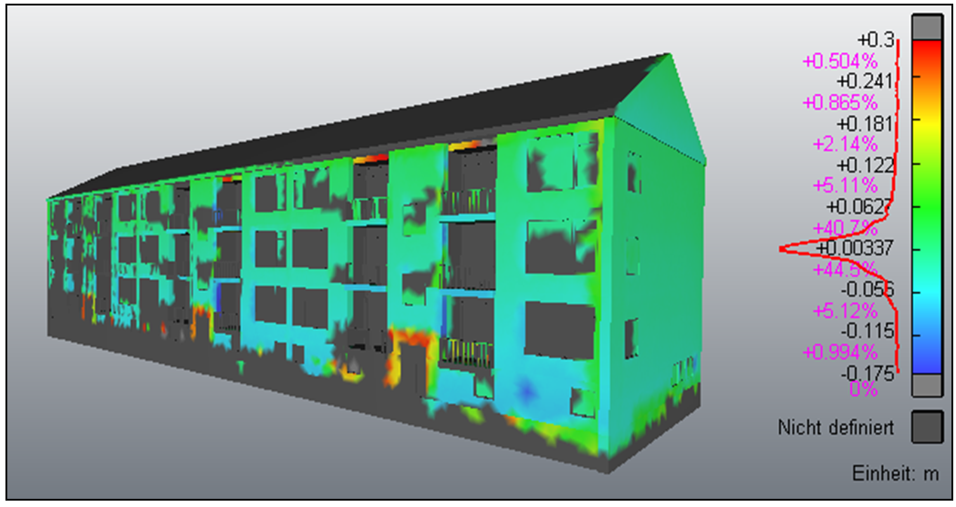
Figure 6: Evaluation of the model overlaid with the point cloud
The process of deviation analysis allows geometrical verification of the 3D model to the as-is situation of the building in order to ensure better accuracy in the model used to carry out renovation planning.
To perform a deviation analysis, definition allowed tolerances between the as-is situation and the 3D BIM model needs to be taken into account