- Anwendungsfälle
- Co-Creation Space
Community
Organisationen
Kooperationspartner

- Anmelden
NOCH NICHT REGISTRIERT?
Registrieren Sie sich für den Use Case Management Service kostenlos, um Ihren ersten Use Case zu erstellen.
Registrierte Benutzer können den Download-Bereich und die Kommentarfunktionen nutzen.
buildingSMART Deutschland e. V. (buildingSMART German Chapter)
All dokuments are licensed as a Creative Commons Attribution-NonCommercial-ShareAlike 4.0 International License
(Attribution-Non-Commercial-ShareAlike 4.0). Further information can be found at
![]()
The documents reflect the current best practice and do not claim to be complete. They should not to be understood in the sense of a generally valid recommendation or guideline from a legal point of view. The documents are intended to support appointing and appointed parties in the application of the BIM method. The documents must be adapted to the specific project requirements in each case. The examples listed do not claim to be complete. Its information is based on findings from practical experience and is accordingly to be understood as best practice and not universally applicable. Since we are in a phase in which definitions are only emerging, the publisher cannot guarantee the correctness of individual contents.
The use case describes the integration of complex technical systems - in this case special laboratory systems - into the BIM process.
A clear and unambiguous interface description and delimitation of the technical/laboratory facilities to the building services engineering is to be mapped, combined with all essential information for the integral cooperation of all project participants in the entire planning process
and life cycle of a building.
The main components of the use case are:
The PG IFC4Lab - the result of a joint initiative of EGNATON e.V. and buildingSMART Deutschland e.V. (aka buildingSMART German Chapter) - has set itself the task of a standardized transfer of information for data exchange in the BIM process of the specialist area of laboratory planning, laboratory equipment and laboratory operation.
All relevant and required data and information in the entire planning and operating process are to be considered with the aim of providing sustainable solutions for both the technical trades and the information management in the BIM process.
The standardization of this information
is one of the greatest challenges.
The definition of "laboratory equipment or technical equipment" includes a large number of equipment systems (laboratory benchtops, laboratory sink units, fume hoods, fume hood cabins, extraction elements, media supply modules)
with special design requirements and material properties, which are suitable for use in a wide variety of laboratories and production plants.
For a clear but also simplified representation of these complex interrelated technical systems in the overall project, the concept of the TecBox was developed.
The TecBox should contain the outer geometric shapes of the respective contiguous system as well as other data such as weight information and map their connection points to the MEP including MSR.
The semantic definition of the TecBox in the BIM model is the representation of a predefined, non-hierarchical and non-overlapping zone within a room or building complex with a predetermined use, function and shape.
It depends on the definition of the technical/laboratory facility as well as resulting transfer interfaces.
It is used for collision planning and for deriving relevant information for architects, planners and operators.
The BIM module "TecBoxContent" was developed for the capture and representation of the specific modular laboratory technical equipment (content of the TecBox).
Further independent equipment, which among other things contribute to the design and specification of the TecBox, is to be captured and represented in the BIM model as EquipmentBox.
Both "BIM" building blocks - TecBoxContent and EquipmentBox - are not explained in detail in this UseCase and are considered separately.
TecBox - as a simplified representation of complex technical equipment

Source: PG IFC4lab
TecBox - transfer points / interfaces as demarcation to the trades of the MEP (ventilation / electrical / media)

Source: PG IFC4lab
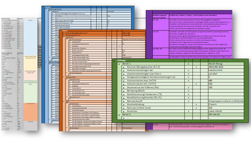
TecBox - Data specification
Data of the TecBox:
TecBox - number
with additional inheritance of the building structure: floor / room number / room name
Transfer points / Interfaces:
TecBox - number = building / floor / room / position.
The information of the transfer points is important for individual TecBox(es) on the one hand and for the overall technical supply representation of a building complex on the other hand.
By displaying the transfer points/interfaces with the integrated performance parameters, the building services trades should be able to determine the overall dimension of the respective building services system (water, wastewater, ventilation systems, etc.) with the corresponding further software systems and to precisely locate the individual media transfer points at an early stage.
In case of performance adjustments of the supply engineering in the planning and operator process, the defined transfer/interfaces can be read out accordingly and evaluated accordingly.
Interaction with the specialist planners makes it possible to continuously update the data and information of the TecBox(es) in the planning process and to ensure fast and precise transfer to other calculation software systems by means of data-based transfer.
Control systems can be integrated to detect and display changes at the transfer/interfaces. This enables the specialist planners to react to changes at an early stage, to adapt the planning accordingly and to save time and costs.
The more detailed Exchnage Requirements will follow soon ->
Important Note: The main Object that might be applicable for TecBox could be ifcSpatialZone. For that reason an additional Predefined Type is really needed.
At the beginning of the planning process, the requirements specified by the customer for the equipment/laboratory and factory equipment as well as instrumentation are translated by the specialist planning department into the specific trade language using various methods.
By means of TecBoxes, which represent a summarized unit of an equipment/laboratory complex within a laboratory or building complex, this information is summarized in a structured but still simplified form and provided with information such as weight, requirements for special structural or building environment qualities as well as technical supply connection parameters.
The technical installations within the TecBox (parallel process - TecBoxContent) form the basis for the design of the TecBox.
By means of transfer of the specialized model of the laboratory technical plant with TecBox methodology, the laboratory and building planning can be realized with complex elements in a short time.
In verification iterations, the results and requirements are systematically integrated into the planning documents by the participants and refined in feedback loops up to the freeze of the planning sections - see process map - sub-process: TecBox definitions.
In particular, the TecBox serves as the core of the interface and requirements definition.
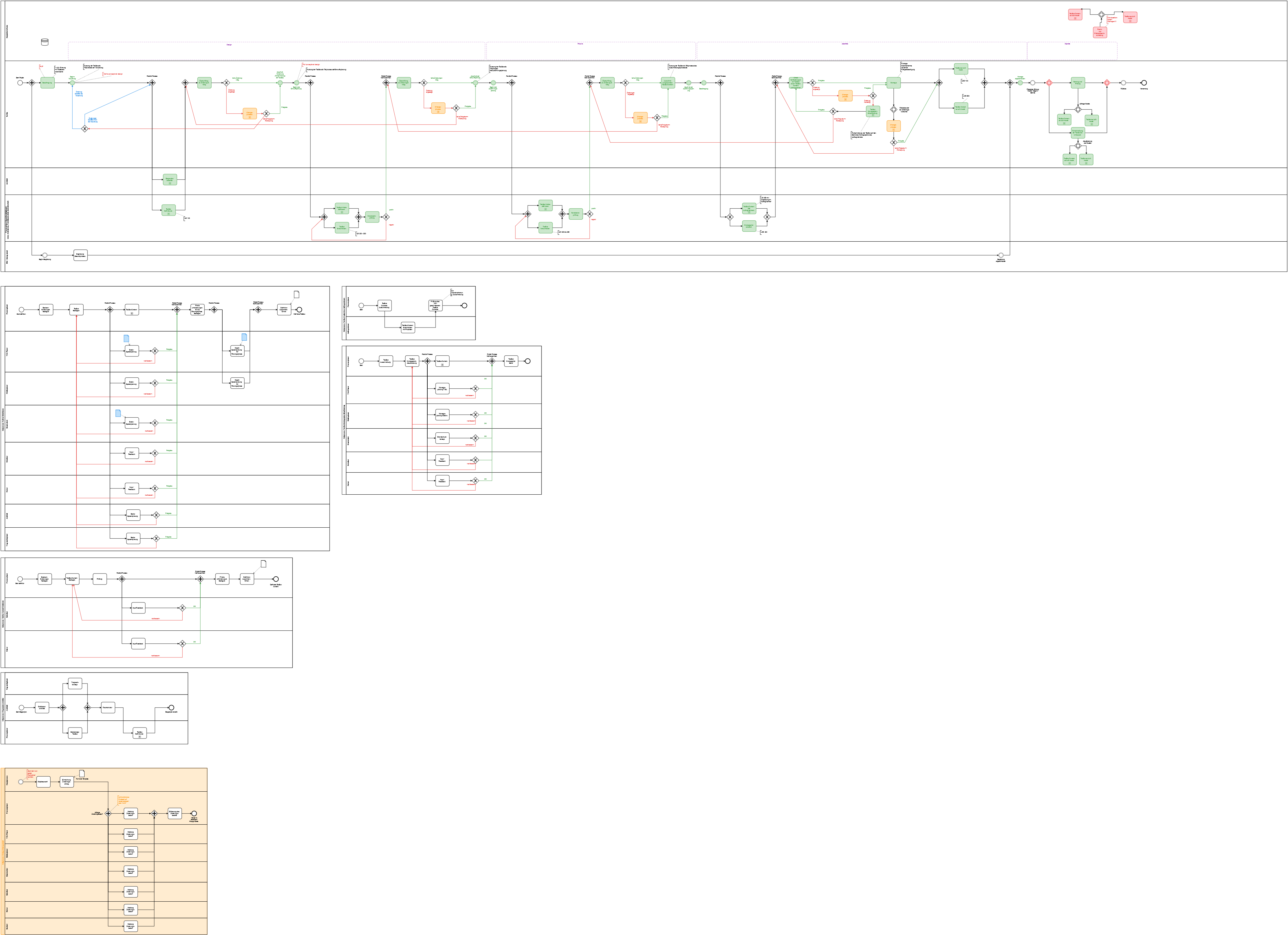
or you may review these BPMN Process Maps (Read-only) under following Link -> https://cawemo.com/share/b0076fc8-92fd-4114-9072-c89f2da0a2c8