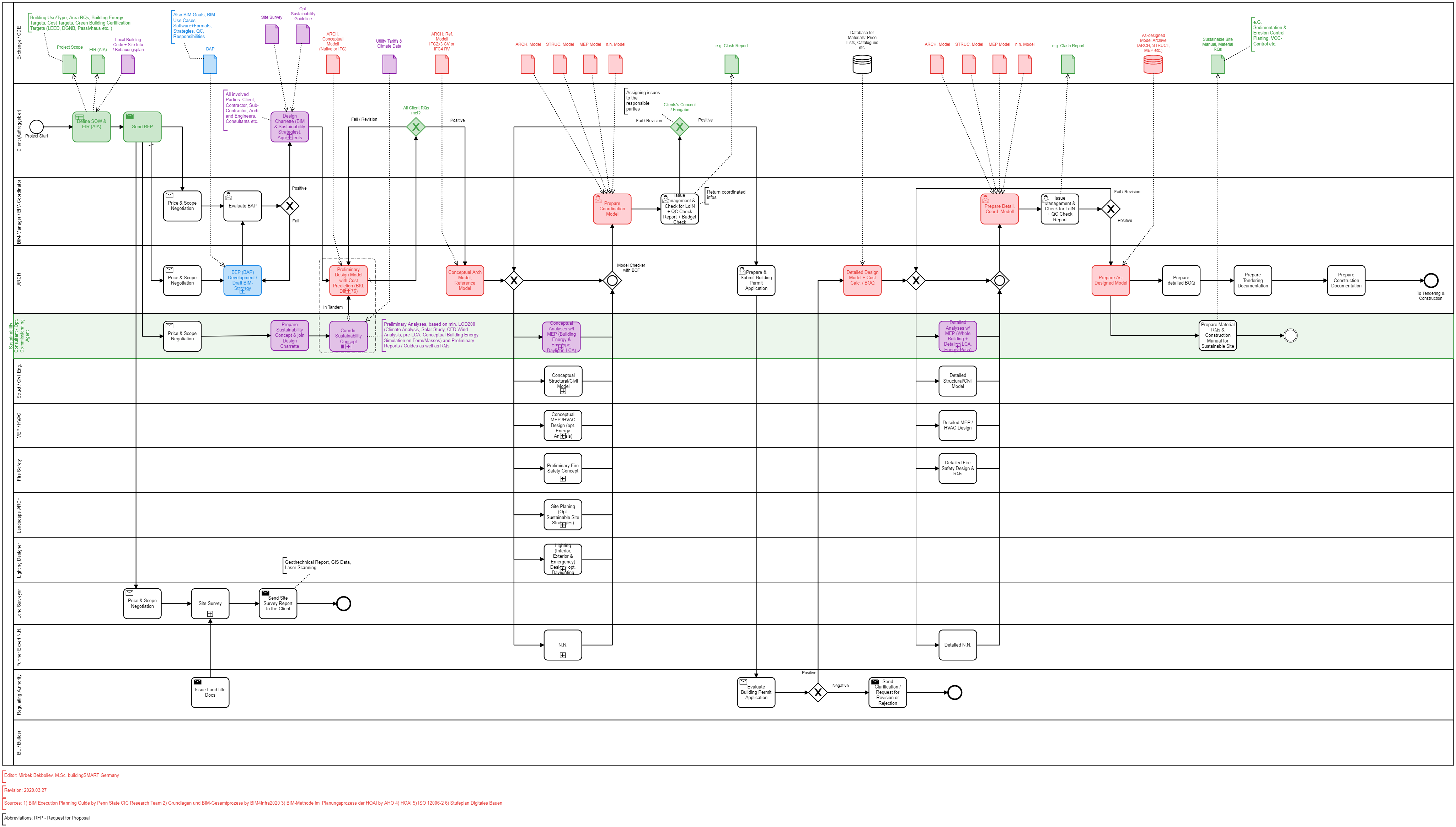
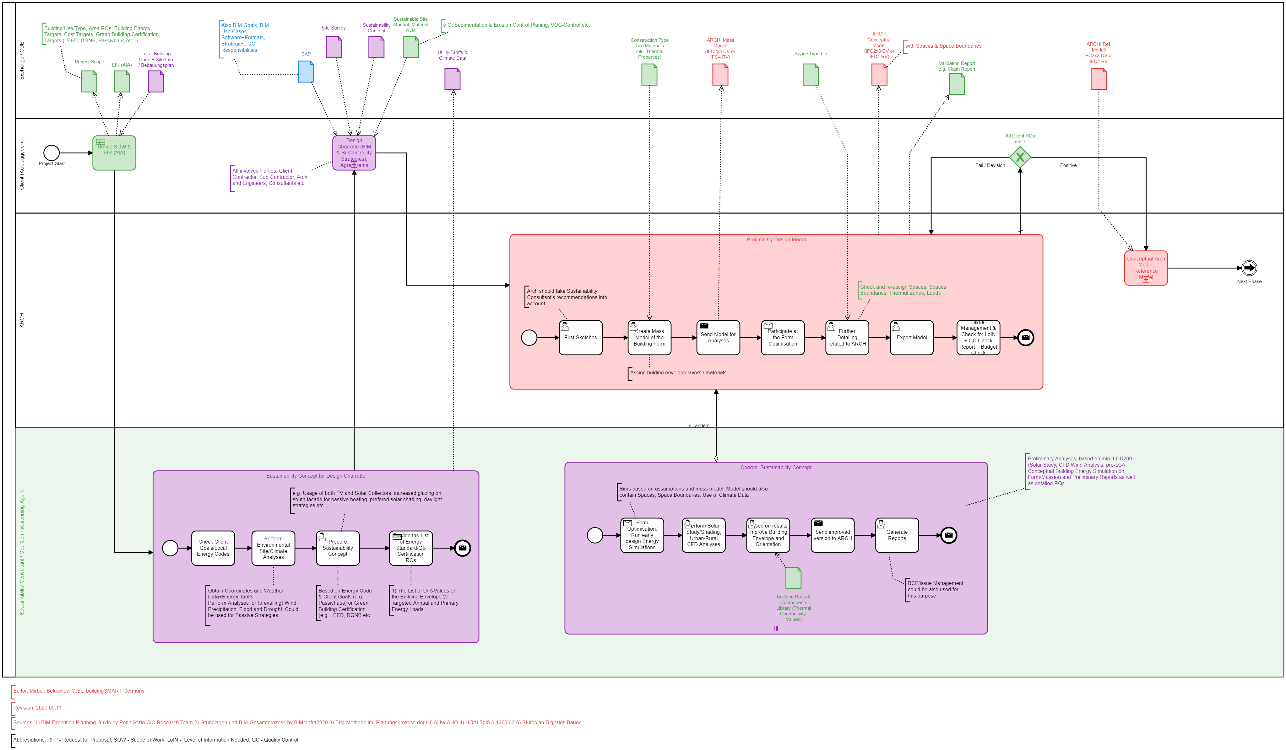
- Cas d'utilisation
- Co-Creation Space
Communauté
Organisations
Partenaires de collaboration

- Connexion
The BIM Collaboration Format (BCF) is a buildingSMART Standard and defines an interface for exchanging information between BIM software systems. For example, errors within the building models can be communicated for Quality Control and Quality Assurance purposes like Collisions (Soft & Hard or Time Clashes) or Modeling.
The exchanged information can be linked to building parts within the building model and consists of essentially two components:
BCF is mainly used in the Design Phases for QC/QA Purposes of the BIM Models and very rarely in Construction or Operation Phases. Following is a classical Example of an Issue when an opening and Duct are not matching as well as not sealed properly. In addition, it is also used for communication purposes.
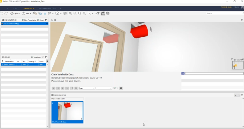
Example of a Hard Clash (Source: Mirbek Bekboliev, 2021)
Yet a general misconception is that the BCF is mainly used for "Clash Detection during the planning stages"...
At the O&M Phases, a BCF could potentially help solve various issues regarding capturing dynamic changes at the building.
The idea is to have an As-built Model, which is expected to reflect the latest building condition before the handover. Further Issue Management Platform would take over the role of Documentation of all dynamic changes related to that model (repair, maintenance, conditions etc.), which could be communicated and documented with the help of BCF and Issue Management. Here is an Illustration of a proposed solution, which is an Inspiration from “What openBIM does for you?” by buildingSMART International / buildingSMART Norway -> https://www.youtube.com/watch?v=KppDDS3KnnM
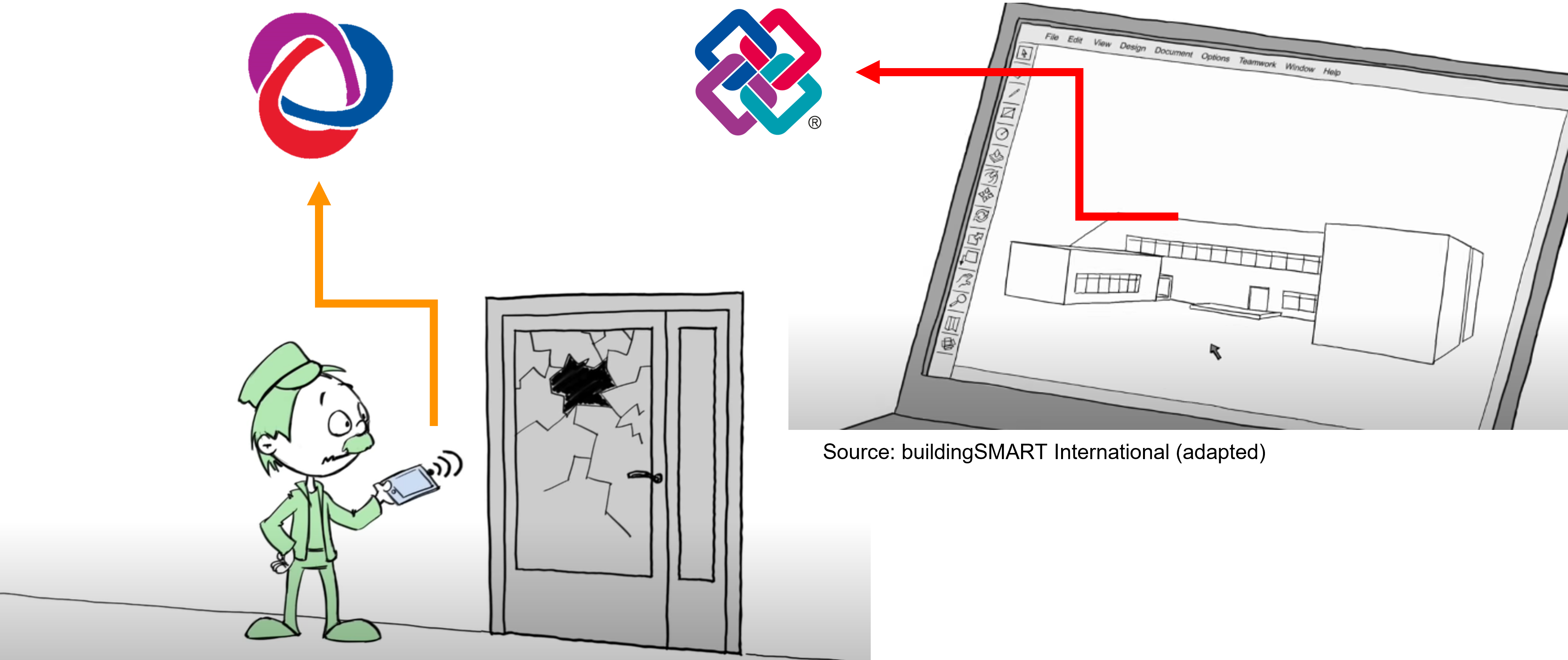
Adapted Illustration for BCF and IFC (Source: buildingSMART International)
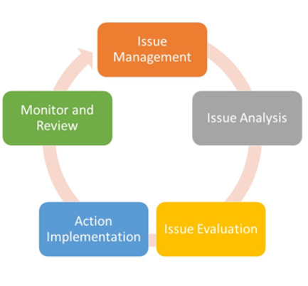
Issue Management and Issue Resolution Process with 6 SIGMA (Source: https://www.whatissixsigma.net/project-issue-management-and-issue-resolution-process)
Case 1 when no drawings exist
Source:?
Case 2 when drawings exist
Source:?
Case 3, when the Model exists
During the construction, assembly and also operation phases, an onsite QC/QA could be performed with various tools like Blower Door Test and Infrared Thermal Imaging...in most of the use cases, potential issues/failures would be photographed and documented on paper or on a printed layout. Thus a big challenge would occur to an asset owner, sustainability consultant and related disciplines to locate them at a later stage.
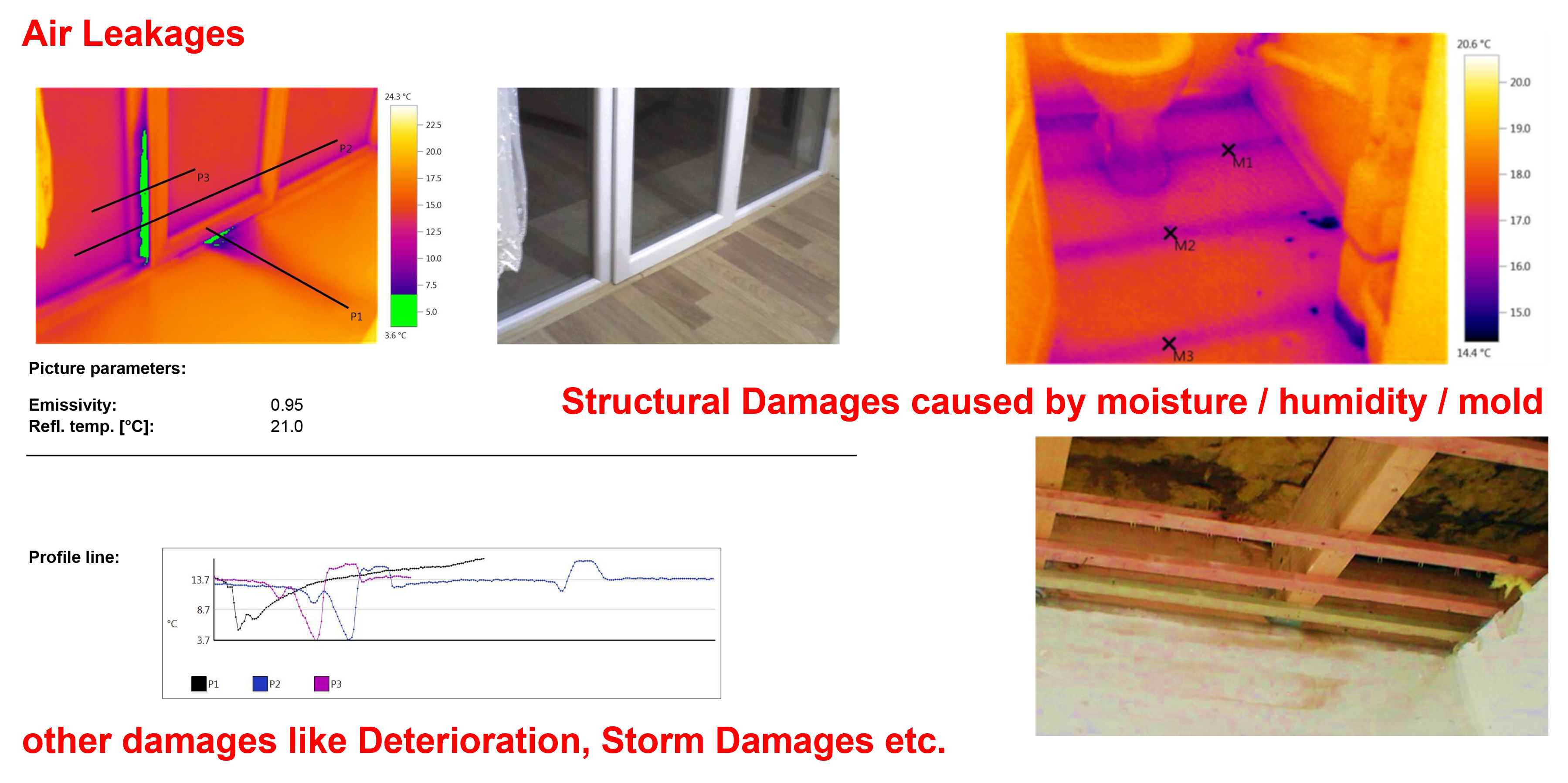
Typical Building Envelope Issues (Source: Mirbek Bekboliev, 2015).
It would not make much effort to locate those issues on a small or medium-scale facility (Building); however, precise location and its current status are vital for the proper operation of the facility.
The usual practice is a manual entry of the Location, Storey, Room / Space ID / Space Name / Description etc.
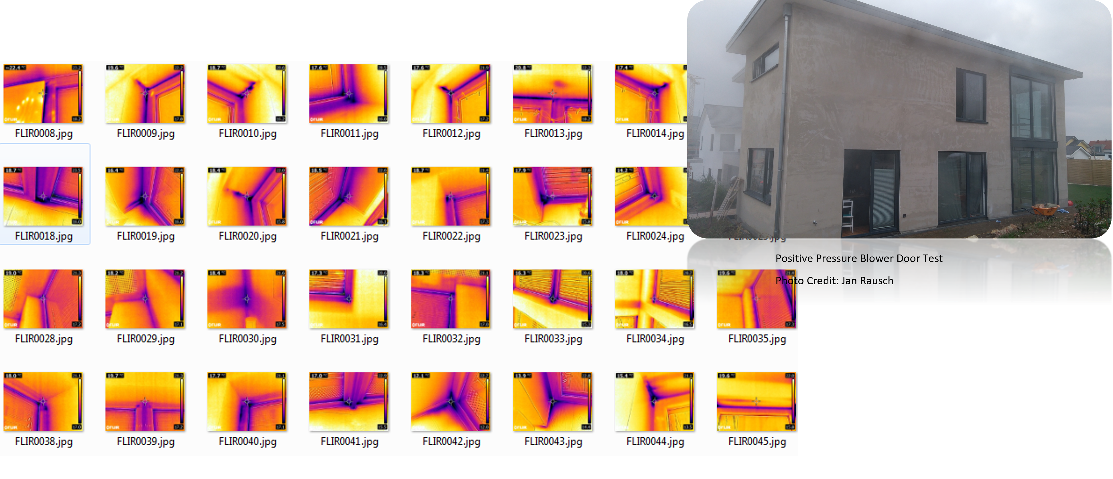
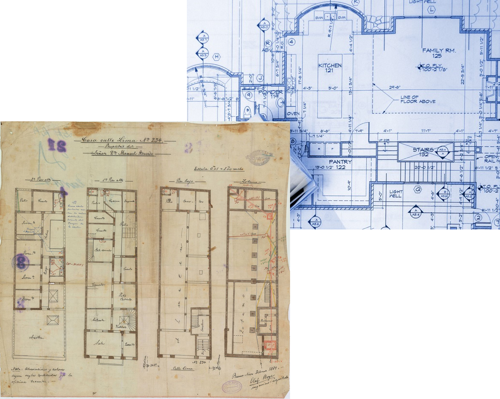
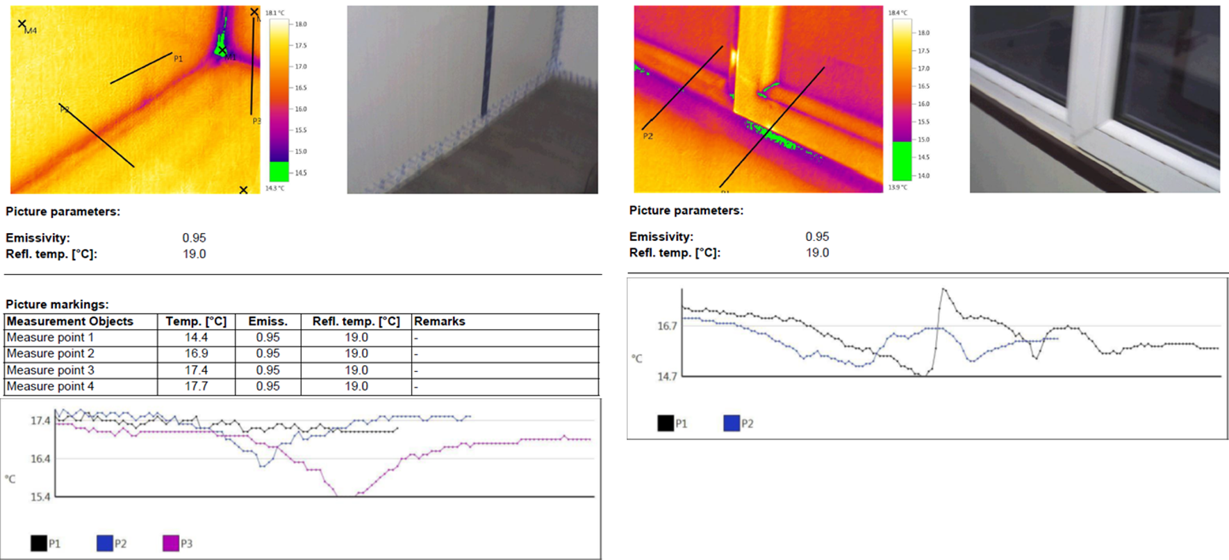
Example for an Airtightness assessment of the building envelope of a Single Family House (Source: Mirbek Bekboliev, 2021)
The more significant challenge occurs by providing a precise location of related building issues in a large-scale building. Like in a small-scale building, a manual entry of the location, Storey, Room / Space ID / Space Name / Description etc., would be performed on paper, yet a large number of storeys, areas and lack of Issue Management would potentially cause lost of information, and as a result, vital steps toward the elimination of those issues may be skipped.
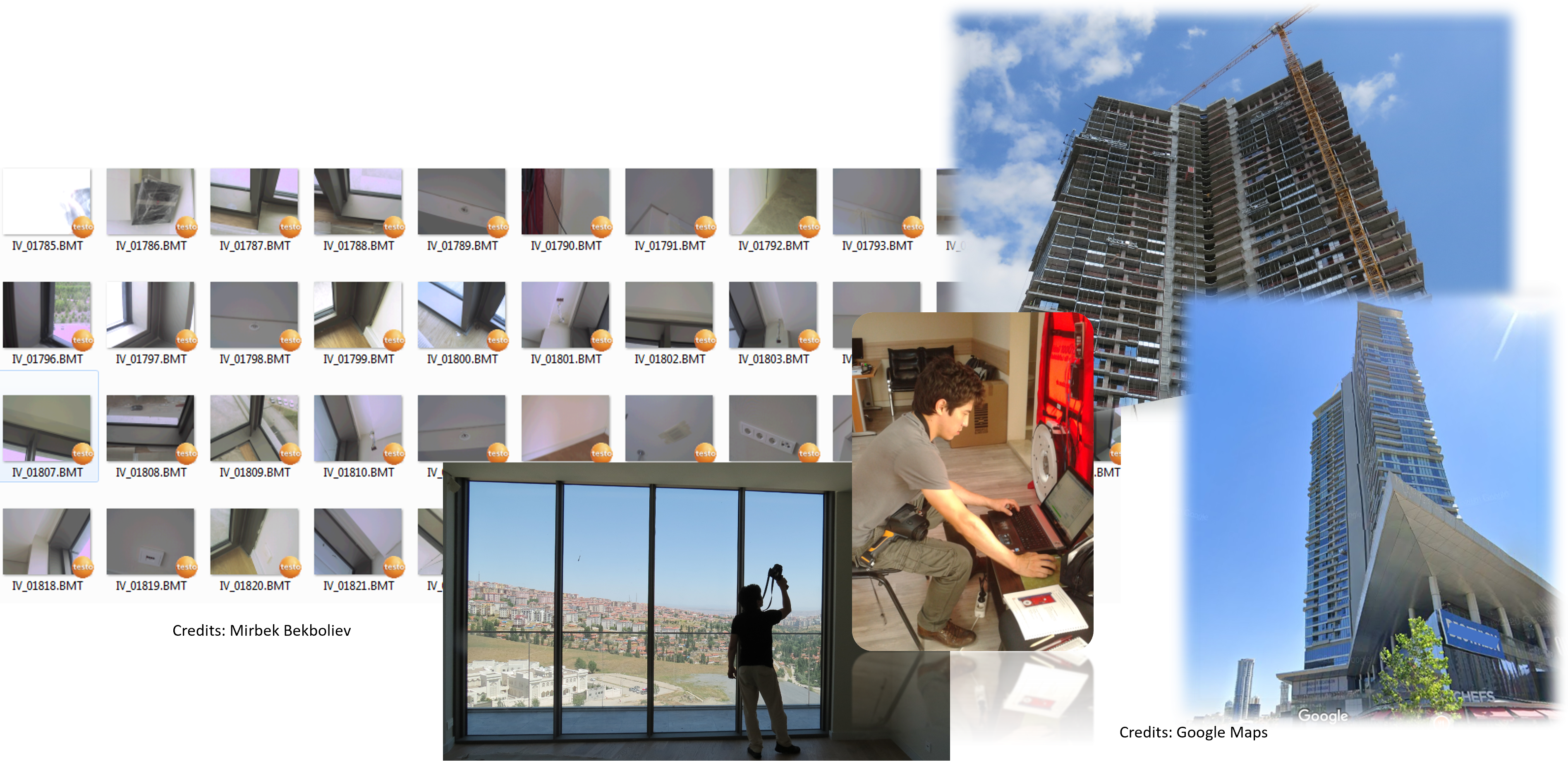
Example for an Airtightness assessment of the building envelope of a Multi Family Residential Block (Source: Mirbek Bekboliev, 2015)
An advantage of a containerized building against a classical building is that the QC/QA would be performed at the factory. Unless it's a modular building, a final assessment would be performed after assembly on site, in a case when 2 or more inter-modal units would be assembled together on site, then QC/QA is inevitable and, in most of the cases, mandatory. Those issues, which occur within the factory, are easy to eliminate, and necessary building parts could be changed/repared in a short time manner. However, it's not a common practice that a building would be tested (Blower Door test or IR Thermal Imaging) in the factory unless it should meet some Building Energy Standards like Passivhaus Standard or local Energy Codes like California Energy Code or even targeting some Green Building Certifications like USGBC LEED or BREEAM etc.). Usually Factory Assembled Buildings are being planned with the help of BIM Methods and Standards. In most of the cases architects, who work closely with Sales Department, would design a building, and further Engineering department would develop their parts based on the reference model. In that case, BCF would be the best approach to exchanging information during the planning stage. Extending its use to manufacturing would also be a win-win situation for the entire team. However, many manufacturing systems currently don't support IFC-Schema...for that reason, some international initiatives are to come. See bSI Building Room for Steel Construction, which aims to update MVD for Steel Fabrication from IFC2x3 Schema into IFC4.3, or the recently released final Standard of IFC4precast covers the precast concrete industry.
In fact, new pioneer factories have started to work with openBIM Standards and implement them not only in steel construction but also in Timber Construction. An IFC Model, in this case, could be easily exported and further used when planning prefabricated buildings, which allows to the extraction of QTo from building models. In fact, those models could also be used for simulations: Whole Building Energy Modeling, Daylight Analyses, Manufacturing and Assembly Sequences 4D & 5D, Thermal bridge Analyses, Asset Operation, Visualisation etc. However, traditional 2D and 3D drawings in most factories remain a common practice.
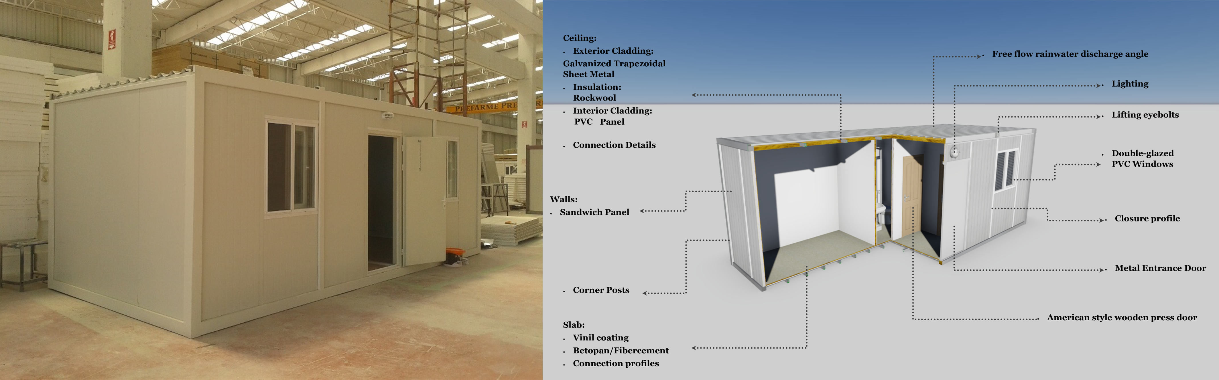
Typical Containerized Building prior to shipment to the site (Source: Mirbek Bekboliev, 2014)
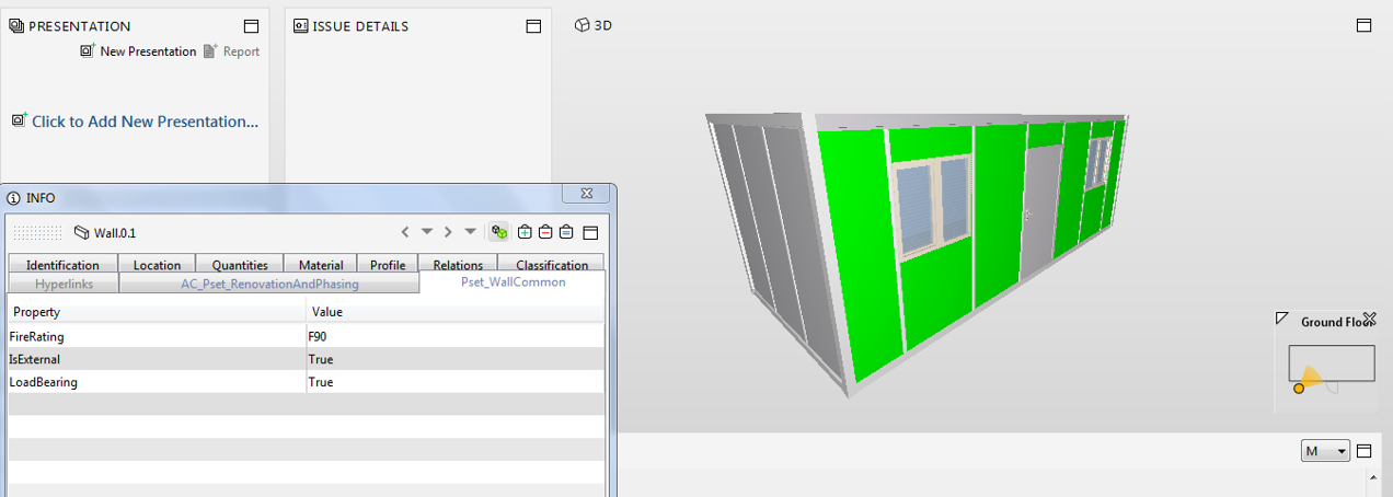
IFC Model of the Typical Containerized Building (Source: Mirbek Bekboliev, 2014)
Narrative: ???
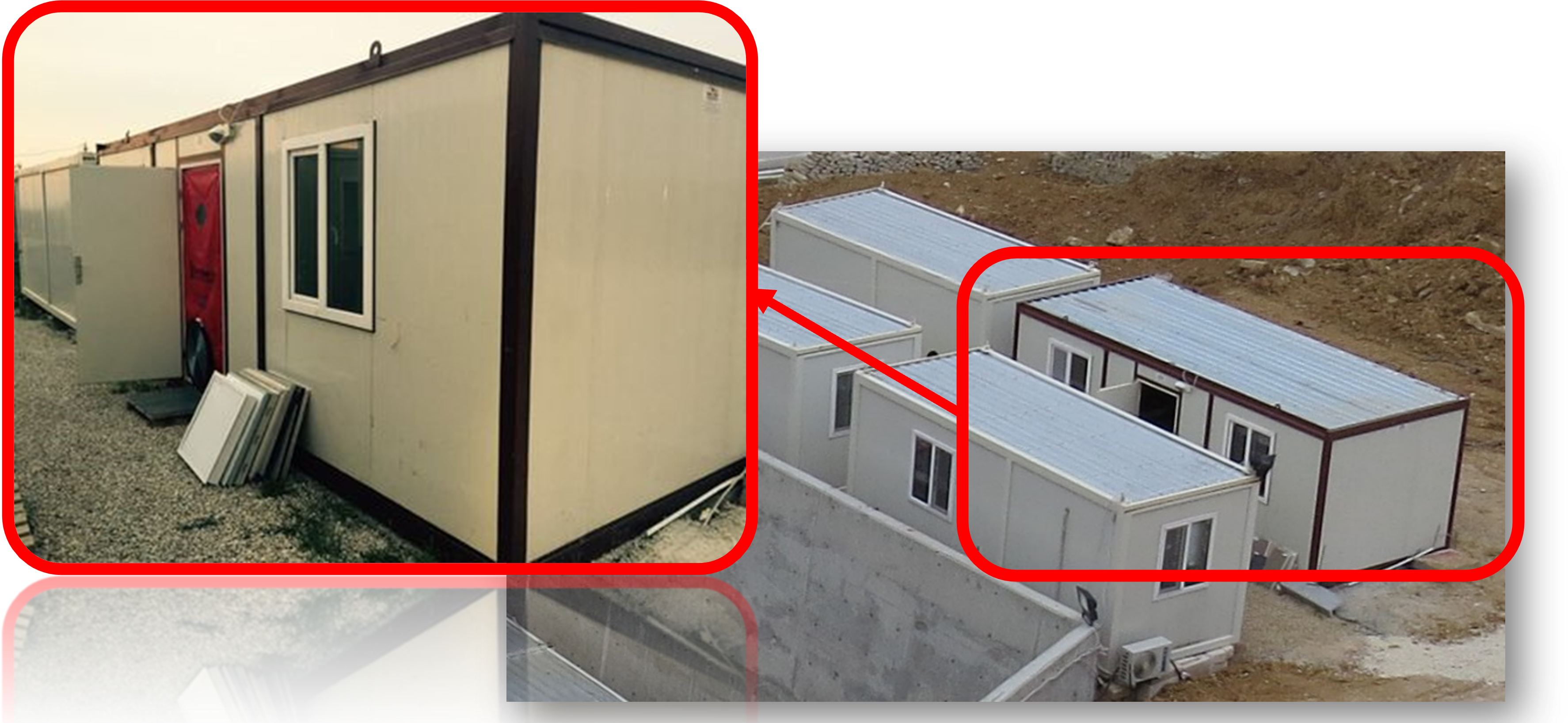
Typical Containerized Building on a construction site, being used as a Forman's Office (Source: Mirbek Bekboliev, 2015)
Issues, e.g. after 10 Years – Energy Retrofit (Renovation)
Narrative: ???
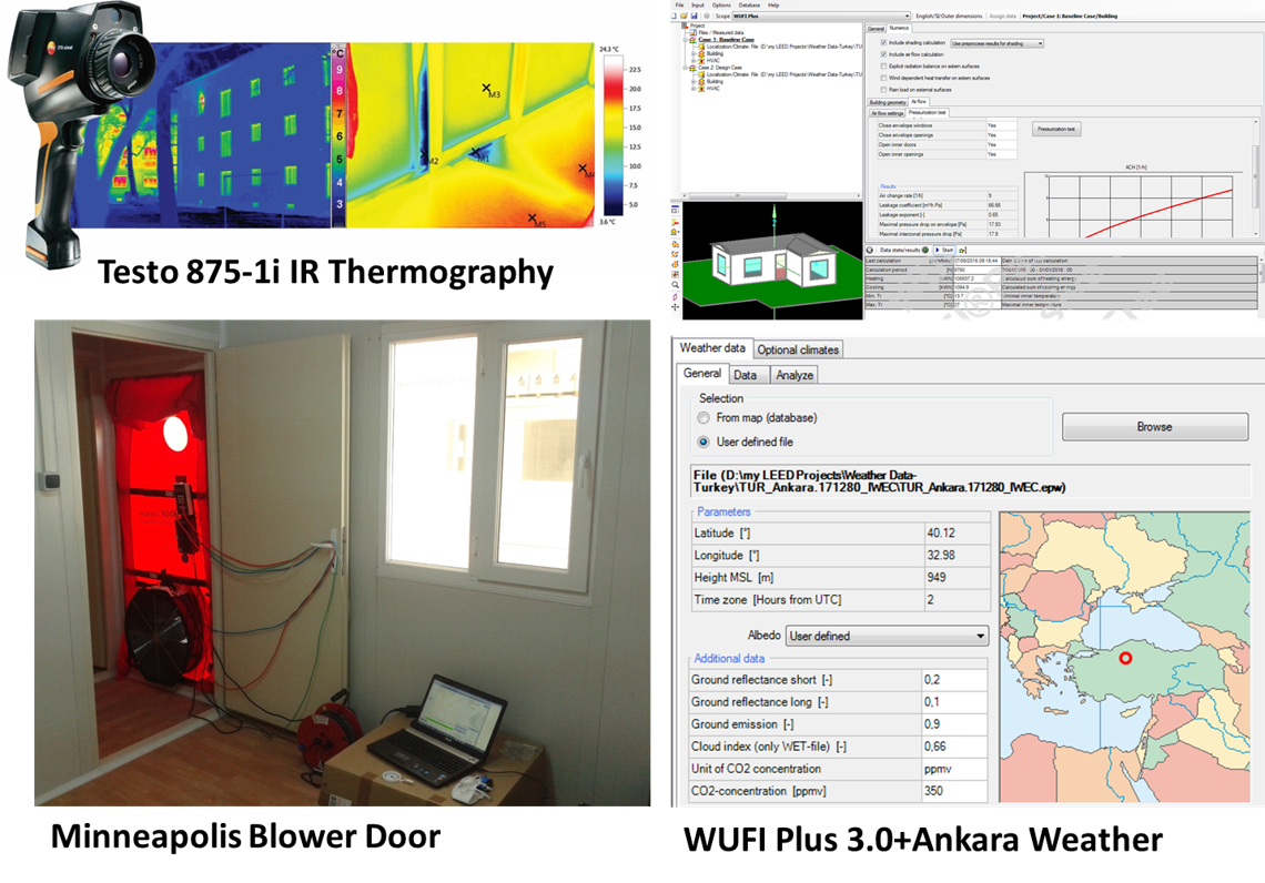
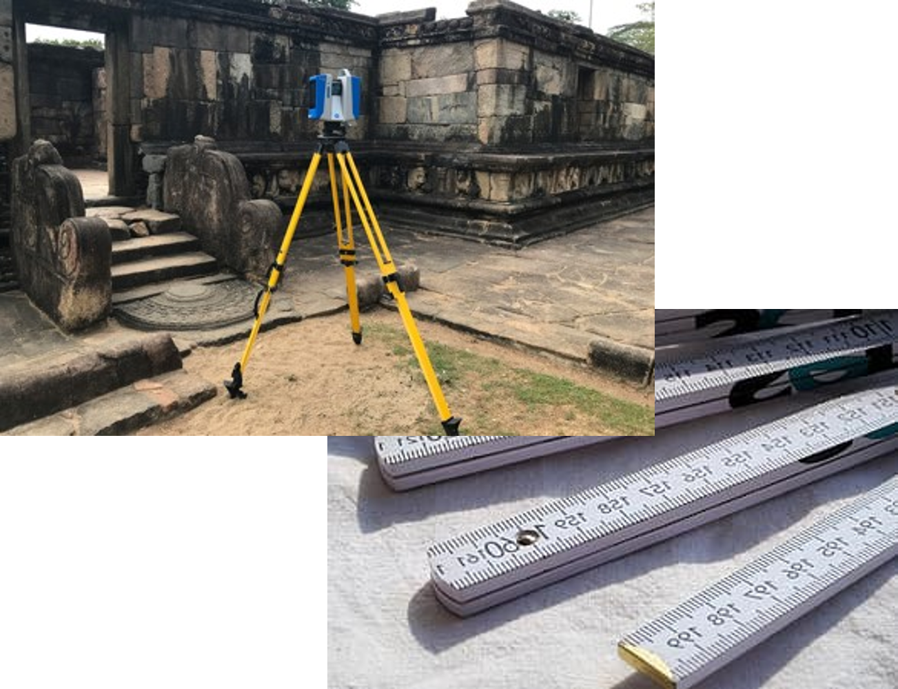
Airtightness Assessment and Documentation Tools (Source: Mirbek Bekboliev, 2015)
Narrative: ???
Why Blower Door and IR Thermal Imaging? Narrative!!
According to Passivhaus Institute, in Germany, a target value for new buildings was first introduced by the German Energy Saving Ordinance (EnEv) on 01.02.2001, currently changed with GEG (Building Energy Code). Specific values for the pressurisation test (n50-values) should not exceed 3 h-1 without ventilation systems and 1.5 h-1 with ventilation.
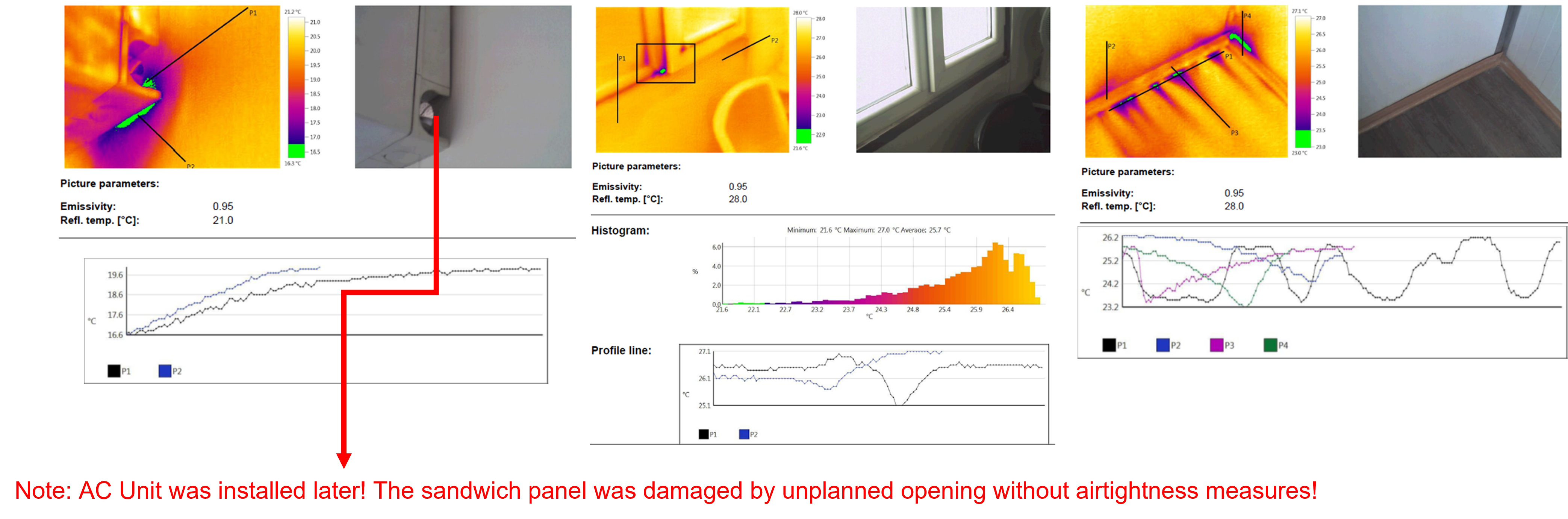
Building Envelope Issues occurred during the assessment of the container building (Source: Mirbek Bekboliev, 2014)
Video 1
Video 2
Video 3
Video 4
Video 5
Narrative: ???
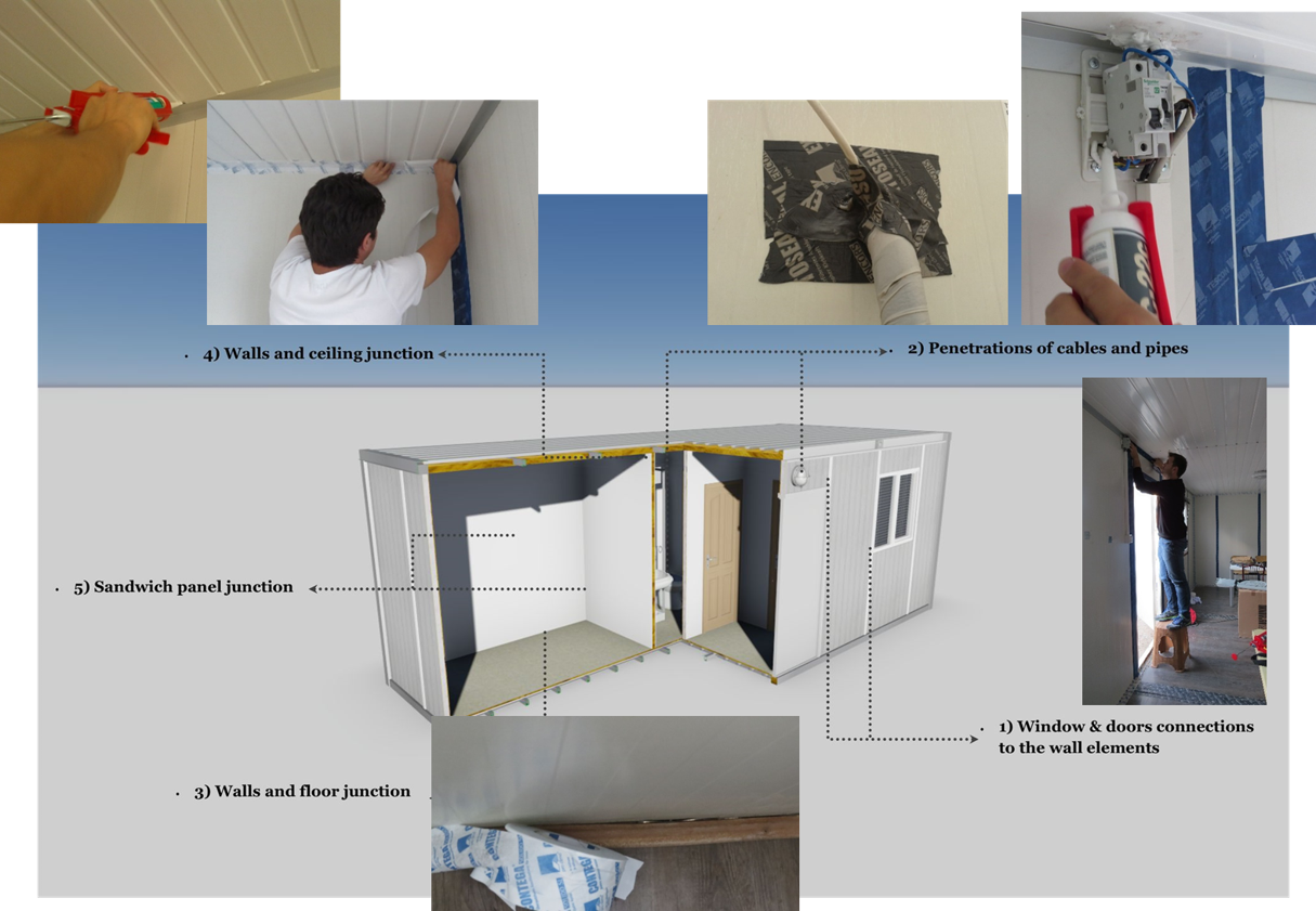
Applied Improvements on Airtightness Level (Source: Mirbek Bekboliev, 2014)
Thermal Imaging during the Blower Door Test of the Containerized Building (Source: Mirbek Bekboliev, 2015)
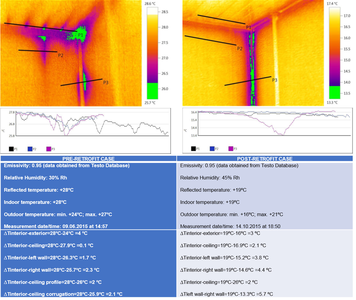
Comparison of the IR Thermal Imaging of the same Container Building Pre and Post Improvement Cases (Source: Mirbek Bekboliev, 2015)
Further Analyses were performed with the IFC Model
Vital Note: Exchange Requirements are Vital. It's important to know which IFC-Schema and its entities and types of simulation software support. E. g. DIALux Evo has been performed for Daylight Analyses, where the IFC2x3 schema is being used. Thus related MVD (Model View Definition) has been used, in this case, IFC2x3 CV.
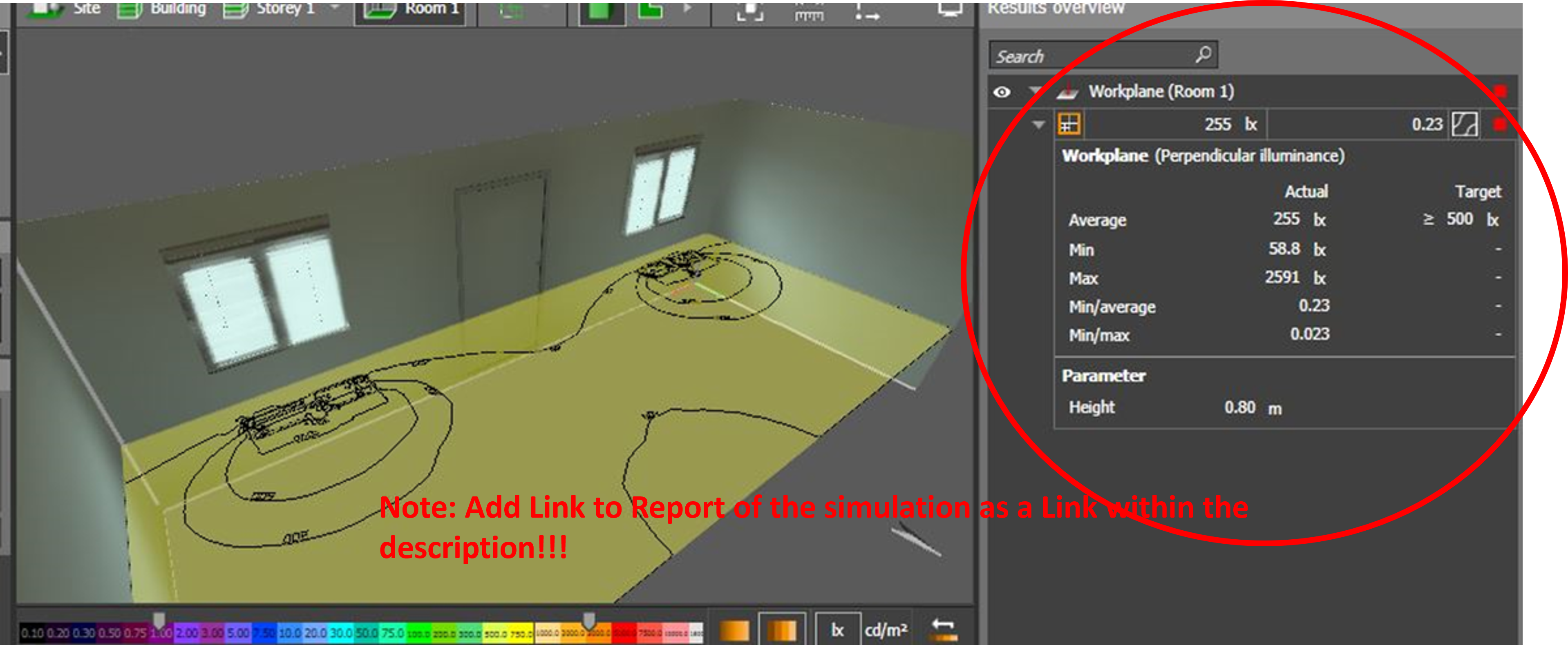
Daylight Simulation based on IFC2x3 CV on DIALux Evo (Source: Mirbek Bekboliev, 2015)
A portfolio manager of multiple schools in Switzerland would like to have documentation about their existing school building to be able to have a better understanding of the condition of their assets. The goal is the data capturing to allow the portfolio manager to better predict the required budget for maintenance and repair costs and better understand the end lifetime of several parts of the building.
Building Info:
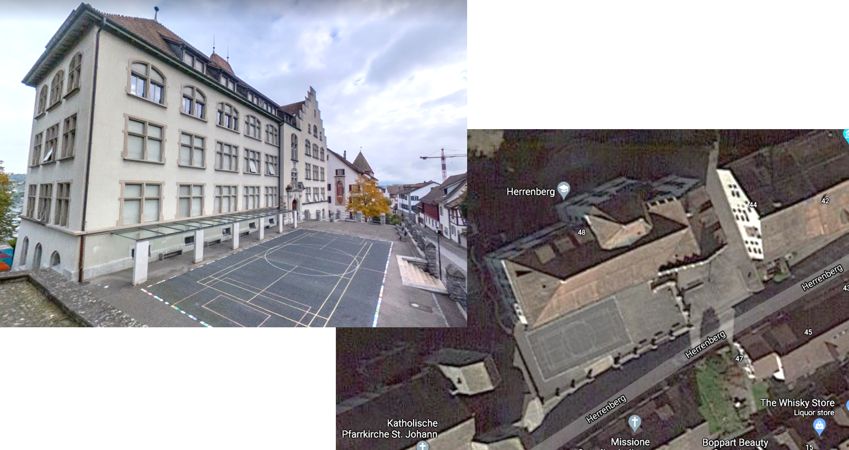
A sample School Building (Source: Gianluca Genova, 2021)
There are multiple ways of capturing data from existing buildings. Different data-capturing technologies and methods have advantages and disadvantages in various conditions like limited light, enough space, accessibility or height limits. Also, these other methods can capture different types of data sets that suit different parts of the building better to get better qualitative data. Usually, a combination of these methods gives the best results to have better documentation for the facility. For interior rooms, 360 cameras in combination with mobile lidar scanning technologies are sufficient, and for exterior surfaces like facades and roofs, drones do a better job.
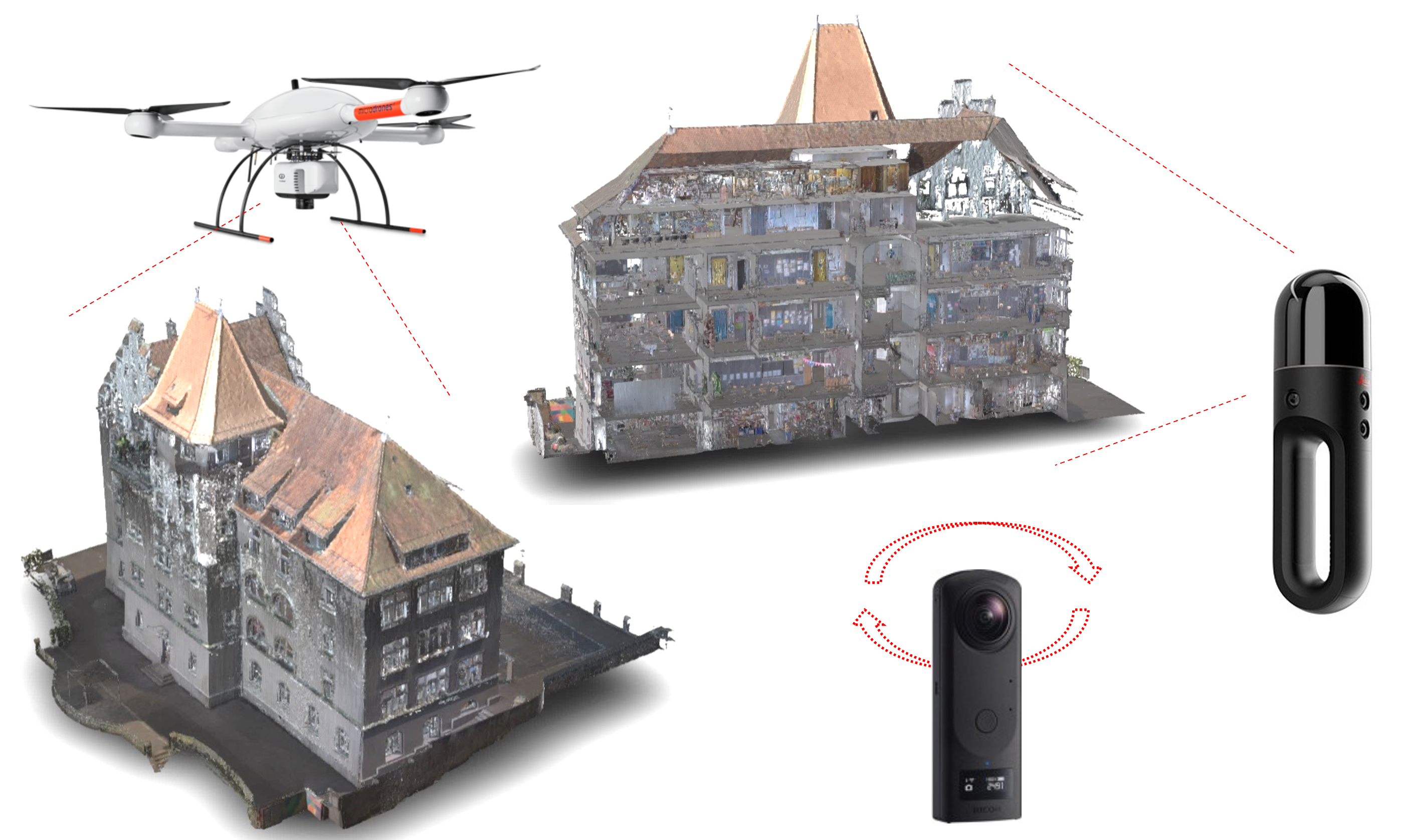
Capturing Tools (Source: Gianluca Genova, 2021)
The mesh model generated by point clouds, besides having accurate dimensions, usually has a lot of distribution on the texture, making it hard to recognise any material or conditional situation about the elements within the building. But having 360 photos from the interior rooms within the mesh model could be handy to compensate for the compromises made by mesh models. If the direction of the 360 pictures and mesh model is synchronized, it also allows one-to-one comparisons with the image and space to understand the asset better.
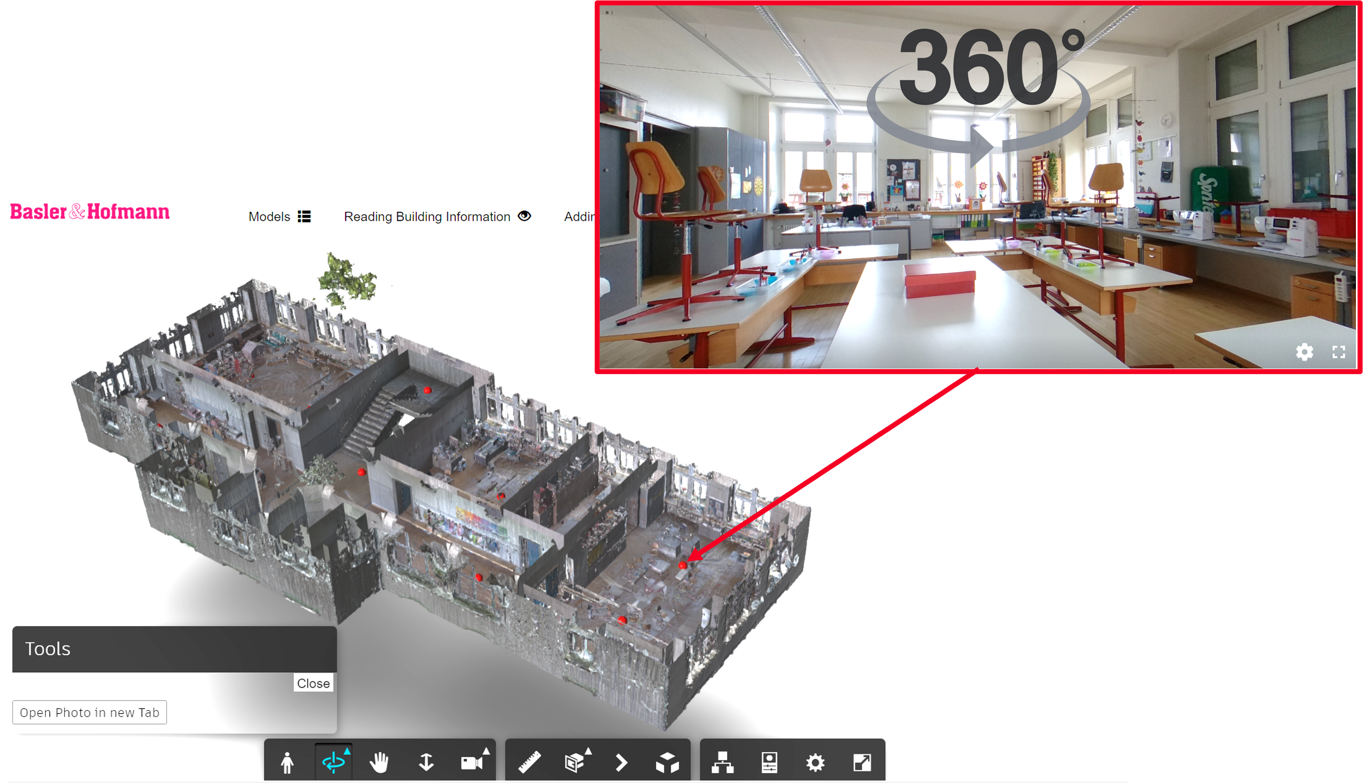
Embedding of Models (Source: Gianluca Genova, 2021)
https://youtu.be/oxcdVMB4Xpc Platform Functions
https://youtu.be/vQdfr-Hg30Q Boundaries
https://youtu.be/XDpg372FDpE Levels
https://youtu.be/Cqh9mV0zPwo Adding Issues
https://youtu.be/KCD11hBBrc8 Adding Issues on a 360 Image
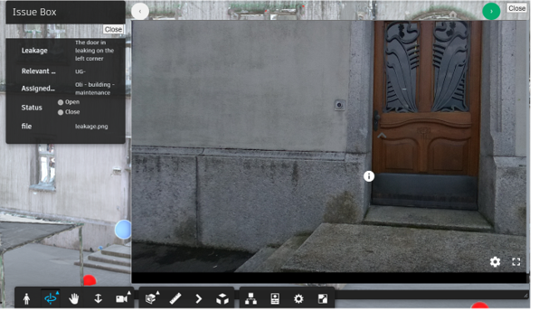
The BIM Collaboration Format (BCF) generally allows different BIM applications to communicate model-based issues. This issue usually contains textual comments, screenshots, related objects and location information. Since we are building a Hybrid model with Mesh and curation spatial elements (ifcSpace or placeholders), this will enable us to use BCF the same way we use our BIM Workflows.
The issues can be converted to BCFs
Issues holder objects can be exported as IFCs
The Issue Holder Objects can be merged with the mesh model and stored in a cloud for further BCF-based applications.
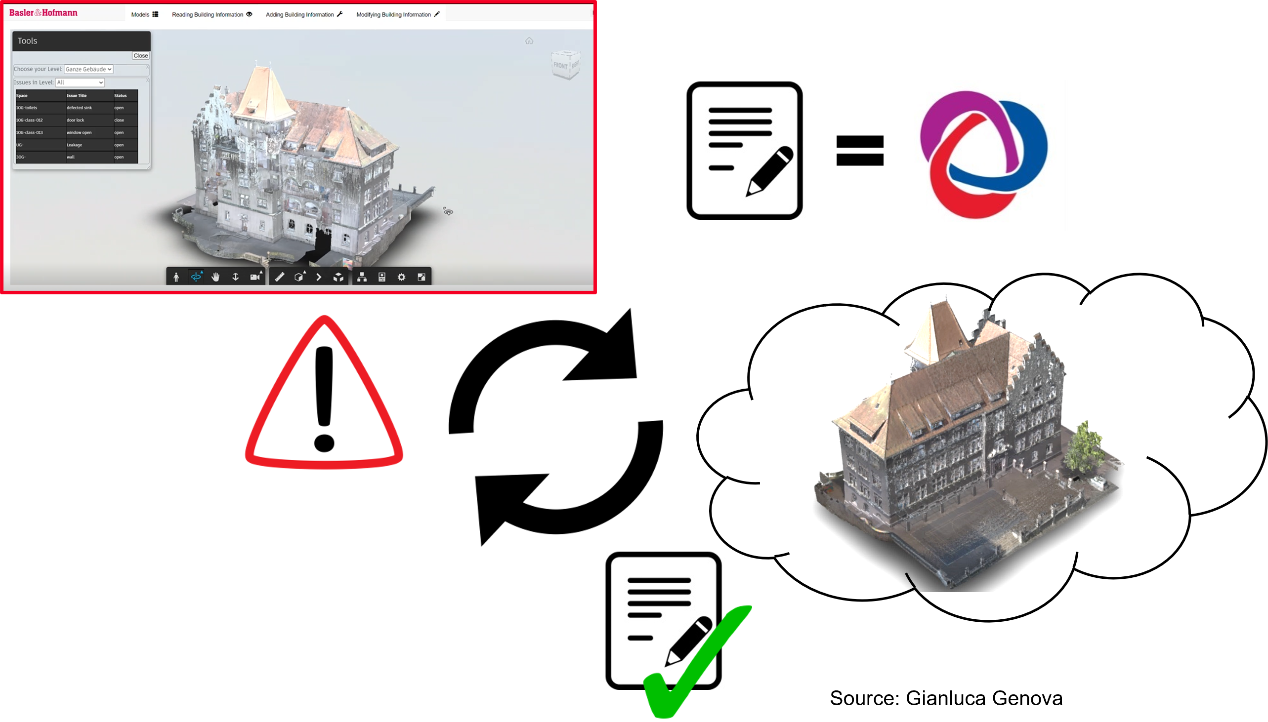
Source: Gianluca Genova, 2021
Narrative by Jeffrey
BCF - BIM Collaboration Format
The BCF standard version 2.1 defines two possible transmission paths:
Here is a short explaination of BCF -> https://www.youtube.com/watch?v=yrm5SrEfSvE
See also -> https://www.buildingsmart.org/standards/bsi-standards/bim-collaboration-format-bcf/
Required Info:
Property: Infiltration -
"Infiltration flowrate of outside air for the filler object based on the area of the filler object at a pressure level of 50 Pascals. It shall be used, if the length of all joints is unknown."
http://ifc43-docs.standards.buildingsmart.org/IFC/RELEASE/IFC4x3/HTML/lexical/Pset_DoorCommon.htm
Property: Infiltration -
Property: AssessmentCondition -
"The overall condition of a product based on an assessment of the contributions to the overall condition made by the various criteria considered. The meanings given to the values of assessed condition should be agreed and documented by local agreements. For instance, is overall condition measured on a scale of 1 - 10 or by assigning names such as Good, OK, Poor."
Property: ThermalConductivity -
"The thermal conductivity of the object. The rate at which thermal energy is transmitted through the material."
Properties: WeatherDataStation, WeatherDataDate, BuildingThermalExposure, PrevailingWindDirection, PrevailingWindVelocity
Source: http://ifc43-docs.standards.buildingsmart.org/IFC/RELEASE/IFC4x3/HTML/lexical/Pset_BuildingUse.htm
Source: http://ifc43-docs.standards.buildingsmart.org/IFC/RELEASE/IFC4x3/HTML/lexical/Pset_SpaceCommon.htm
Properties: InfiltrationDiversitySummer, InfiltrationDiversityWinter, TotalCoolingLoad, TotalHeatingLoad
Source: http://ifc43-docs.standards.buildingsmart.org/IFC/RELEASE/IFC4x3/HTML/lexical/Pset_ThermalLoad.htm
Vital required Infomation:
Qto_BuildingBaseQuantities
Source: http://ifc43-docs.standards.buildingsmart.org/IFC/RELEASE/IFC4x3/HTML/lexical/Qto_BuildingBaseQuantities.htm
Note: Unfortunately following properties are not applicable to the windows or doors...
Property: Leakage -
"Air leakage rate."
Property: LeakageClass -
"Nominal leakage rating for the system components."
Further Notes:
All dokuments are licensed as a Creative Commons Attribution-NonCommercial-ShareAlike 4.0 International License
(Attribution-Non-Commercial-ShareAlike 4.0). Further information can be found at
![]()
The documents reflect the current best practice and do not claim to be complete. They should not to be understood in the sense of a generally valid recommendation or guideline from a legal point of view. The documents are intended to support appointing and appointed parties in the application of the BIM method. The documents must be adapted to the specific project requirements in each case. The examples listed do not claim to be complete. Its information is based on findings from practical experience and is accordingly to be understood as best practice and not universally applicable. Since we are in a phase in which definitions are only emerging, the publisher cannot guarantee the correctness of individual contents.
PAS ENCORE INSCRIT?
Inscrivez-vous au Service de Gestion des Cas d'Utilisation gratuitement pour commencer à créer votre premier cas d'utilisation.
Les utilisateurs inscrits peuvent utiliser la zone de téléchargement et les fonctions de commentaire.