
- Cas d'utilisation
- Co-Creation Space
Communauté
Organisations
Partenaires de collaboration

- Connexion


The Model Setup IDM Georeferencing BIM IDM is aimed at all building/ infrastructure/ built asset modellers, to robustly establish the guiding model set-out parameters - map location and site configuration - for their respective asset (BIM or Digital Engineering) models. The document therefore defines a standardised way for setting up a multi-disciplinary geo-referenced project model using the IFC open standard format data. The document also defines a standard way of incorporating Cadastral data as a starting point for representing land legal ownership, zoning and planning data.
The document focusses on geo-referencing principles and includes examples for IFC2x3, IFC4 and IFC4x3ADD2 formats embedding geo-referencing data.
bSI maturity level
The Model Setup Information Delivery Manual (IDM) has been extended for infrastructure modellers working on projects spanning large distances where the requirements are to supply IFC files of digital engineering (BIM) data in an Earth based coordinate system such as longitude and latitude, or Map (projection) coordinates. Such data is referred to as being georeferenced.
As this is the standard for most long road and rail projects, this is often referred to as Horizontal or Linear BIM. This Information Delivery Manual adds the requirements for setting up such a multi-disciplinary georeferenced project so that data can be interchanged using the IFC 4x3 format.
Section 4: Georeferencing Vertical BIM and Section 5: Georeferencing Horizontal BIM amplify technical issues and provide extended examples now covering all the major use-cases for a majority of asset types. Section 7: Supplying Map Coordinates Using IFC gives guidance of specific usage of the new entities.
Section 9.6 Using Georeferencing Parameters in IFC 2x3 provides naming guidelines for ePsts for all georeferencing entities required when using the IFC2x3 format (replacing the previous Table 4).
Section 10: Georeferencing Check List assists users with a comprehensive checklist of the data required for all entities.
Version 2.0 of the technical report had been re-structured as a User Guide and published in January 2020 by the buildingSMART International Building Room and buildingSMART Australasia. These are now merged into a single document.
The original version of the report was published in August 2018 with the title Model Setup IDM (Information Delivery Manual).
Opportunities addressed and created value
Initial discussions with industry identified the lack of knowledge with regards to georeferencing and the strong interest in this subject in the user base in Australia. Discussions during the project confirmed the global status of this topic, including lack of knowledge in users, and, for advanced infrastructure users, the necessity of the approach set out in the User Guide.
The IFC4x3 update extends Georeferencing capability to infrastructure developments with major contributions from the German Chapter and continued consultation from international experts.
What has been done?
The project was presented at several bSI International Summits and meetings which elicited strong support for this approach in linear infrastructure projects. In particular, at the Tokyo bSI Summit the project was presented as part of the Building Room agenda and received considerable support including that from a study undertaken in Germany.

The development and relaease of IFC4x3 required an extension of geo-referencing to support the new infrastructure asset types Roads, Railways, Bridges etc to the IFC standard.
Further recommendations
This Model Setup IDM Georeferencing BIM IDM is a useful addition to the schema and will have direct international benefit by allowing much greater reliability for collaborative model sharing.
Attached is a discussion document [Model Setup IDM_Extensions for Georeferencing.pdf] with several suggestions for possible further improvements.
Contact
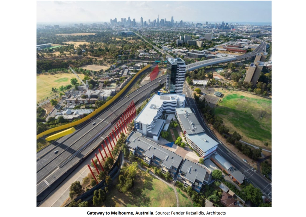
Demonstration Scenario for Model Setup IDM
Model Setup IDM_Geo-referencing BIM (v3.0)
All documents are licensed as "Creative Commons Attribution-NonCommercial-ShareAlike 4.0 International License" as Attribution - non-commercial distribution - under the same conditions
For further information see: creativecommons
These documents do not claim to be complete. Nor are they to be understood in the sense of a recommendation or guideline that is generally valid from a legal point of view, but are intended to support the client and contractor in applying the BIM method. The use cases must be adapted to the specific project requirements. The examples given here do not claim to be complete. Information is based on practical experience and should therefore be regarded as best practice and not generally applicable. As we are in a phase in which definitions are only just emerging, buildingSMART cannot guarantee the accuracy of individual contents.
PAS ENCORE INSCRIT?
Inscrivez-vous au Service de Gestion des Cas d'Utilisation gratuitement pour commencer à créer votre premier cas d'utilisation.
Les utilisateurs inscrits peuvent utiliser la zone de téléchargement et les fonctions de commentaire.

Overview
The primary concept detailed below is the creation of a digital BIM template or skeleton of a proposed or to be modified asset, that needs to be shared amongst the now common, many specialists in the implementation of modern facility developments. Its function is to give a precise description of the site and its location for local, GPS and geo-referencing, and a framework for the set-out and spatial configuration of the built asset. The model setup task can occur at different stages of a project, depending on the type of owner (i.e. developer versus say a public hospital agency), or infrastructure context where the setup may be a different and more important priority. In the Scenarios below we specify some obvious examples but recognise specific projects may be in a different sequence or priority.
Project Roles
A Client (or owner, public or private) we consider has two generic choices; a common development path where the asset is speculative and intended for resale and no further interest in the built asset; or an owner who has a long term ownership of a portfolio of properties (such as a University campus, hospital complex, commercial office space provider, or a transport facility such as an airport or road network) where the agency etc has an ongoing operational or maintenance responsibility.
In this latter case a Facility Manager (or Building Manager) may perform the role, and there is the likelihood that a well documented asset (master) plan comprising full surveys and particularly in infrastructure, map referencing & geo-location have been established. A project brief issued by such client organisation may have done a significant amount of preplanning, and in the special cases of the extension or integration of an existing asset, refurbishment or renovation may be wholly responsible for the model set-out.
A Lead Designer may be an Architect, Engineer, Landscape planner, Project Manager or an Advisor. They have the role to define the specific location of the asset on a site, to define its spatial nature and extent of the asset(s) and to provide an overall asset concept. For the model set-out the naming and broad spatial geometrical framework are the essence of the exchanged data. Often this information may be adjusted or refined during the Inception and Feasibility life-cycle phases. The model set-out may change during early project stages, but will be frozen once detailed design, documentation or construction phases commence.
A Land Surveyor is responsible for undertaking the detailed site survey, accessing and confirming cadastral and title particulars, and for developing a site model. Traditionally these data would be in a 2D drawing; in the Model Setup IDM this information is a component of the asset digital model, focussing on the description of the site, nature of the terrain, geology, natural features, climate zone, and often government Planning aspects such as land use types, development controls, easements etc. as well as adjoining site and existing or proposed built asset relationships.
A Land Registry is responsible for the description of Cadastre and Land Title (ownership) its key activities. This defines the boundaries of lots or parcels of land under private, Crown or government ownership. Cadastral data is currently a 2D description (with varying national standards) but is moving to a 3D description firstly to describe strata title (where an owner has multiple parts of a generally multi-storey building (eg a car space, apartment space(s) and an access space). However this 3D spatial context is also present in subterranean developments and also transport systems (roads, railways…) which overlap in the airspace. A Council (or Local Government or Authority, Borough, Commune, Planning Department etc) has the role of controlling the types of development within its boundaries. Such Zoning and Development controls limit the types and scope of built assets or activities that can be provided.
Terms and Concepts
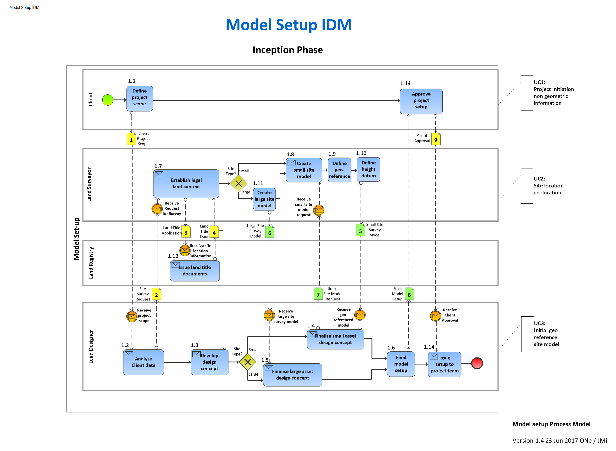
2.1 Define Project Scope
The Client specifies the type of asset to be developed, the design brief and the site information on which the asset is located.
2.2 Analyse Client Data
Following an analysis of the brief for the new asset, the Lead Consultant requests from the Land Surveyor a survey be undertaken of the project site.
2.3 Develop Design Concept
The Lead Consultant develops a design concept for the chosen site in accordance with the Client Brief, and authoritative site information.
2.4 Finalise Small Asset Design Concept
In the case of a project with a master design (linear infrastructure, large asset development) model in Eastings/Northings coordinates, a small site model in Cartesian coordinates and appropriate Helmert transformation for a local Asset design model is requested from the Land Surveyor. Design Team members may/will provide design and configuration information for the chosen site setout (including local origin, rotation and elevation) and their data is integrated with the design model. This may take multiple iterations to achieve the final project configuration. The (adjusted) small site model from the Land Surveyor is integrated with the design model and a final design prepared.
2.5 Finalise Large Asset Design Concept
The Lead Consultant receives from the Land Surveyor a large site model in Eastings/Northings coordinates and develops a final design collaborating with other design Team members who may/will provide design and configuration information for the chosen site setout.
2.6 Final Model Setup
The Lead consultant finalises the asset model setup integrating the surveyor’s model of the site, and sets a framework for the setout and spatial configuration of the proposed asset design.
This comprises:
For a small site, the Lead Consultant will validate the geo-reference
2.7 Establish Legal Land Context
The Land Surveyor reviews the Client brief and submits an application to the Land Registry to obtain a copy of the Land Title(s) and cadastral data for the Lot(s).
2.8 Create Small Site model
Based on the Title and cadastral information, the Surveyor undertakes an on-site survey, proving the Lot boundaries, an as-built survey to capture existing buildings, terrain, site features, identification of easements, existing improvements, utilities, structures and other features of the property and it's surrounds. Identifiable points, such as the corners of the property will assume local coordinates based on the site model.
2.9 Define Geo-reference
The Land Surveyor conducts a control survey to connect the site to survey marks with known coordinates in the Eastings/Northings grid coordinate system. The Surveyor uses the coordinates of the identifiable points to compute a Helmert transformation for the local site model and inserts the geo-referencing data
2.10 Define Height Datum
The Land Surveyor adds the reference to the National Height Datum to be used and adds the height shift relative to the model's origin point (benchmark) and local height.
2.11 Create Large Site model
Based on the Title and cadastral information, the Surveyor creates a site model for the linear or large asset based on Eastings/Northings coordinates. As needed the Surveyor undertakes lot surveys, identifies benchmarks, proving boundaries, identifying site features, identification of easements, existing improvements, utilities, structures and related matters.
2.12 Issue Land Title Documents
The Land Registry issues the Land Title documents, with Lot identification, cadastral boundaries, ownership and easement & related data.
2.13 Approve Project Setup
The Client approves the project model setup and work can commence for the next project phase to build a federated model
2.14 Issue Setup to Project Team
The Lead Consultant distributes the approved Model Setup for the project team to create the required discipline specific project models.